A figure 234 – Basler Electric BE1-11g Manuel d'utilisation
Page 403
Advertising
9424270994 Rev N
379
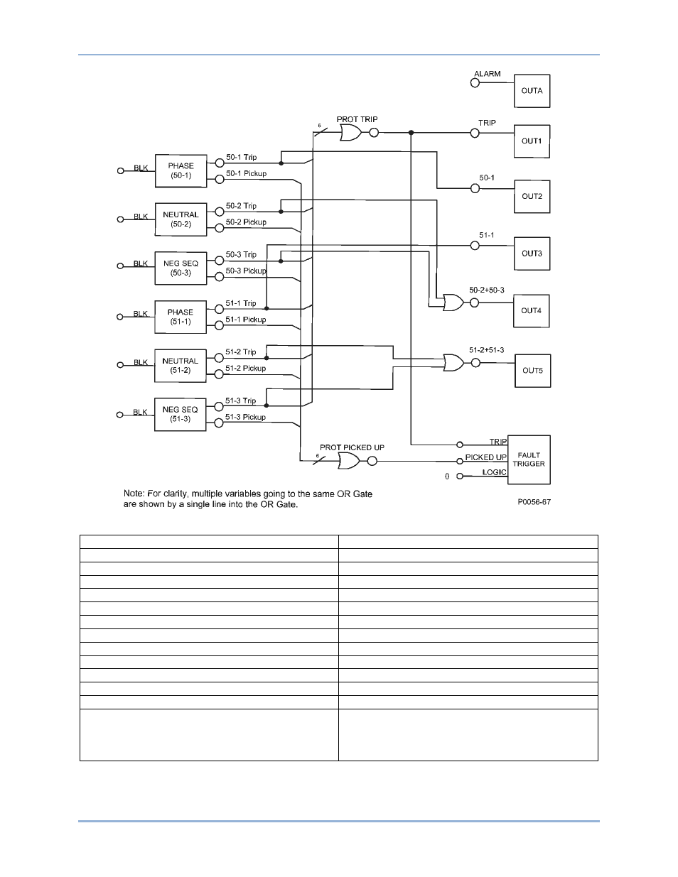
Figure 234. Diagramme logiquede la logique par défaut
BLK
CLIGNOTANT
PHASE
PHASE
Trip
Déclenchement
Pickup
Enclenchement
NEUTRAL
NEUTRE
NEG SEQ
SÉQ NÉG
PROT TRIP
DÉCLENCHEMENT PROT
ALARM
ALARME
OUT
SORTIE
PROT PICKED UP
PROT ENCLENCHÉE
PICKED UP
ENCLENCHÉ
LOGIC
LOGIQUE
FAULT TRIGGER
DÉCLENCHEUR DE DÉFAUT
Note: For clarity, multiple variables going to the
same OR Gate are shown by a single line into the
OR Gate.
Remarque : Pour plus de clarté, de multiples
variables allant vers la même passerelle OU (OR)
sont représentées par une seule ligne allant vers
la passerelle OU.
BE1-11g
BESTlogic
™Plus
Advertising
Ce manuel est liée aux produits suivants: