Grass Valley TTV 1707 Manuel d'utilisation
Page 175
Chapter 4 - Channel control unit
175
Description
THOMSON TTV1707 / CCU DT500
User manual
B1707M00LD
September 2000
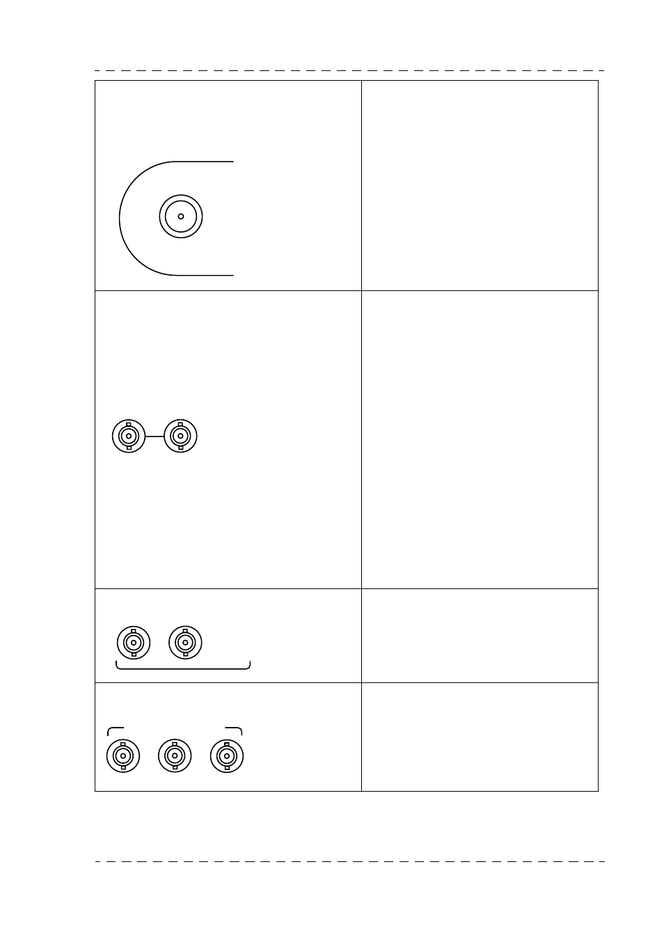
8. «TRIAX» receptacle
Connection of the TRIAXIAL cable
connected to the camera control unit.
The cable transmits the various signals
and the camera power supply.
Output voltage: 52V DC
I max: 3 A
9. «GEN LOCK EXT. REF» receptacles
The «loopedthrough» reference signal
input. The signal is not loaded in the
Channel Control Unit. Input level: 1 V
peak-to-peak / 75 Ohms.
• As a general rule, the signal must be of
"composite video" type to control the
composite and digital signals at the
output from the channel control unit
(link J92 set to ON on the GEN-
LOCK/VIDEO board.
• If the reference signal does not a
"Burst", place link J92 on the GEN-
LOCK/VIDEO board to OFF position.
The composite signal subcarrier is then
slaved with respect to the composite
sync signal.
Refer to the INSTALLATION chapter for
equipement phase alignment.
10.«COMPOSITE V.B.S.» receptacles.
Encoded PAL or NTSC signal outputs.
Levels: 1 V peak-to-peak/75 Ohms.
11.«SERIAL DIGITAL OUTPUT» receptacles Serial digital signal outputs:
4:2:2, 270 Mbits.
CAMERA
Receptacles:
•
LEMO 75
Ω
•
LEMO 50
Ω
•
FISCHER
•
KINGS
•
DAMAR HAGEN
GENLOCK
EXT. REF.
Receptacles
Type: P2189-A
P/N: T9003306
COMPOSITE
V. B. S.
1
2
Receptacles
Type: P2189-A
P/N: T9003306
1
2
3
SERIAL DIGITAL OUTPUT
Receptacles+câbles
Type:
98230x-021-009.0
P/N: T6000091