1 - installation of ccu in rack – Grass Valley TTV 1707 Manuel d'utilisation
Page 125
125
Installation of ccu in rack
THOMSON TTV1707 / CCU DT500
User manual
B1707M00LD
September 2000
This chapter provides general information concerning installation of the equipment.
For a description of the various connectors, refer to the chapter specific to each
subassembly. The OCP40 /OCP42 panels are described in a specific manual.
2.1 - INSTALLATION OF CCU IN RACK
The DT500 CCU is fitted in a 19"rack:
1. Either alone or with an accessory of dimension 1/2 19" (vectorscope, oscilloscope,
etc.) using the assembly kit for CCU DT500 in 19" racks, part number
BDT050701AA.
2. Or two DT500 CCU’s side by side using kit part number BDT05700AA.
2.1.1 - Installation of a Channel Control Unit with a 1/2 19" accessory
EQUIPMENT AND TOOLS REQUIRED
• Rack installation kit part number BDT05701AA containing various accessories,
• A screwdriver.
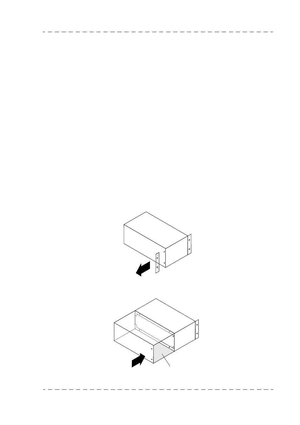
2.1.1.1 - Fitting of accessory to the left of the Channel Control Unit
1. Remove the LH lug from the CCU DT500 by unscrewing both attaching screws.
2. Couple the accessory rack to the LH side of the CCU DT500 with the lugs located at
the back of the CCU DT500.
++7
++7
accessory rack