2 - back panel – Grass Valley TTV 1707 Manuel d'utilisation
Page 172
172
Chapter 4 - Channel control unit
Description
B1707M00LD
September 2000
THOMSON TTV1707 / CCU DT500
User manual
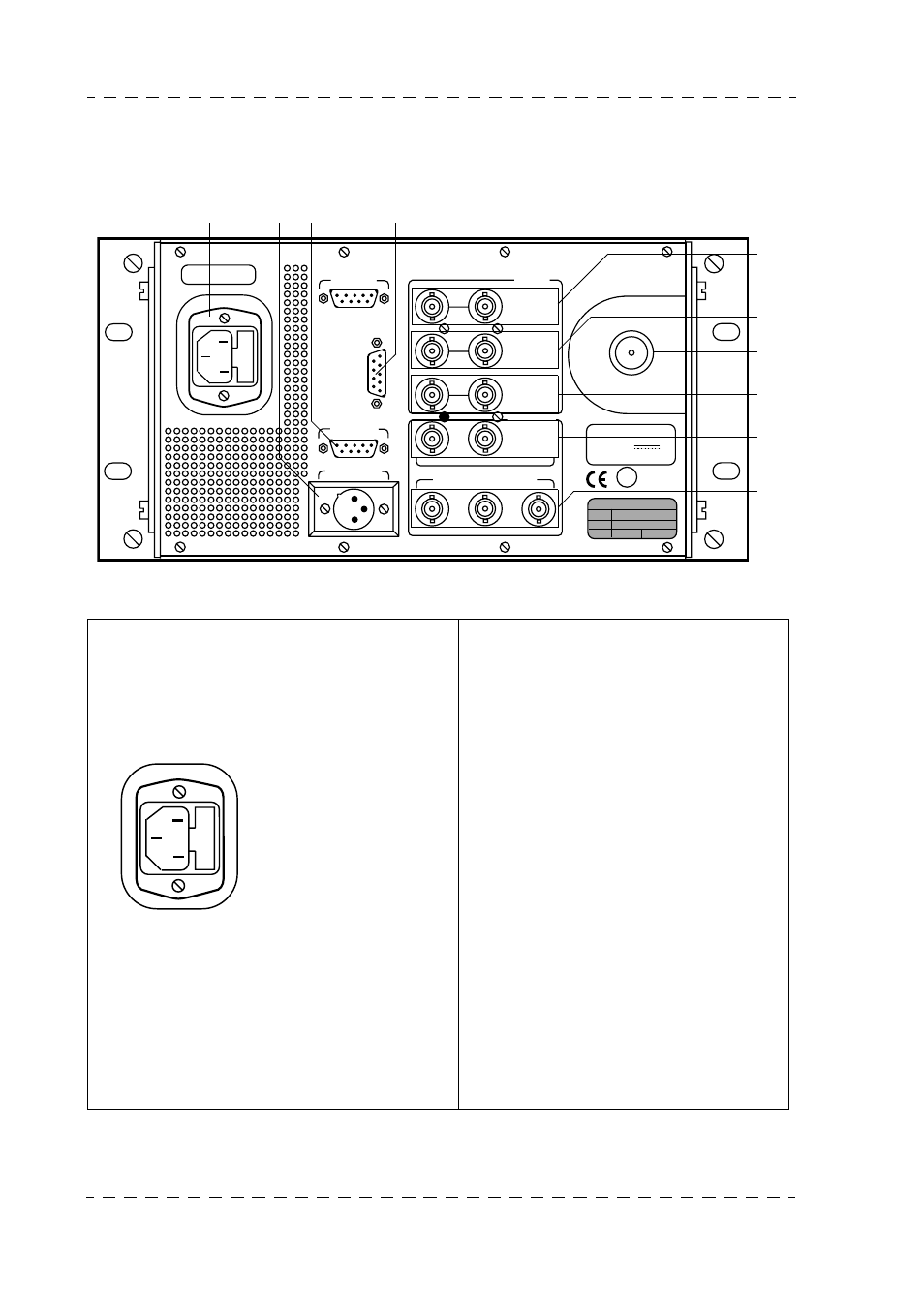
4.1.2 - Back panel
1. Mains socket and fuses
Connection to mains cable
According to equipement serial number,
the power supplies equipping the Channel
Control Unit are:
• Bivoltage (fitted with an automatic
switching system: 100 to 125 V AC
and 200 to 240 V AC 50 or 60 Hz). In
this case, no adaptations are required in
terms of mains voltage.
• Or monovoltage 100 to 125V AC or
200 to 240V AC 50 or 60 Hz.
Before connect the CCU to the mains,
to make sure of the equipement opera-
tion voltage. This voltage is indicated
on the label located on the CCU rear
panel.
FUSE CHANGING
The fuse is located in the mains connector
on the back of the Channel Control Unit.
Disconnect the mains plug for access to
fuse.
This connector also contains a spare fuse.
VIDEO RET 1
PROMPTER
VIDEO RET 2
GENLOCK
EXT. REF.
COMPOSITE
V. B. S.
1
1
2
2
3
SERIAL DIGITAL OUTPUT
OUTPUT
INPUT
CAMERA
INTERCOM
MIC OUTPUT
REMOTE
TALLY
2
3
1
N
DATA + DC OUT
53V
3A MAX
T6,3A H 250V
6
7
8
9
10
11
1
2
3
4
5
N
1
3
2
2 fuses:
- Equipment protection fuse
- Spare fuse.
Fuse type:
110V or 220V: Value T 6,3
AH 250V
P/N: T9000671
1 : Neutral
2 : Ground (connected to chassis ground)
3 : Phase