Grass Valley TTV 1707 Manuel d'utilisation
Page 127
127
Installation of ccu in rack
THOMSON TTV1707 / CCU DT500
User manual
B1707M00LD
September 2000
6. Attach the LH lug of the CCU DT500 (removed in 1) to the left of the accessory rack.
7. Place the accessory in the accessory rack (accessory attachment is to be adapted
according to its type and brand).
8. Place the CCU DT500 + accessory in the 19" rack at the desired location and attach
by means of the two lugs.
2.1.1.2 - Fitting of accessory rack to the right of the Channel Control Unit
The principle is identical to the previous procedure, but the six 4 mm dia. screws joining
the two assemblies are to be fitted from inside the CCU DT500. This implies that the CCU
power supply unit must be removed.
1. Remove the right-hand lug from the CCU DT500 by unscrewing both attaching
screws.
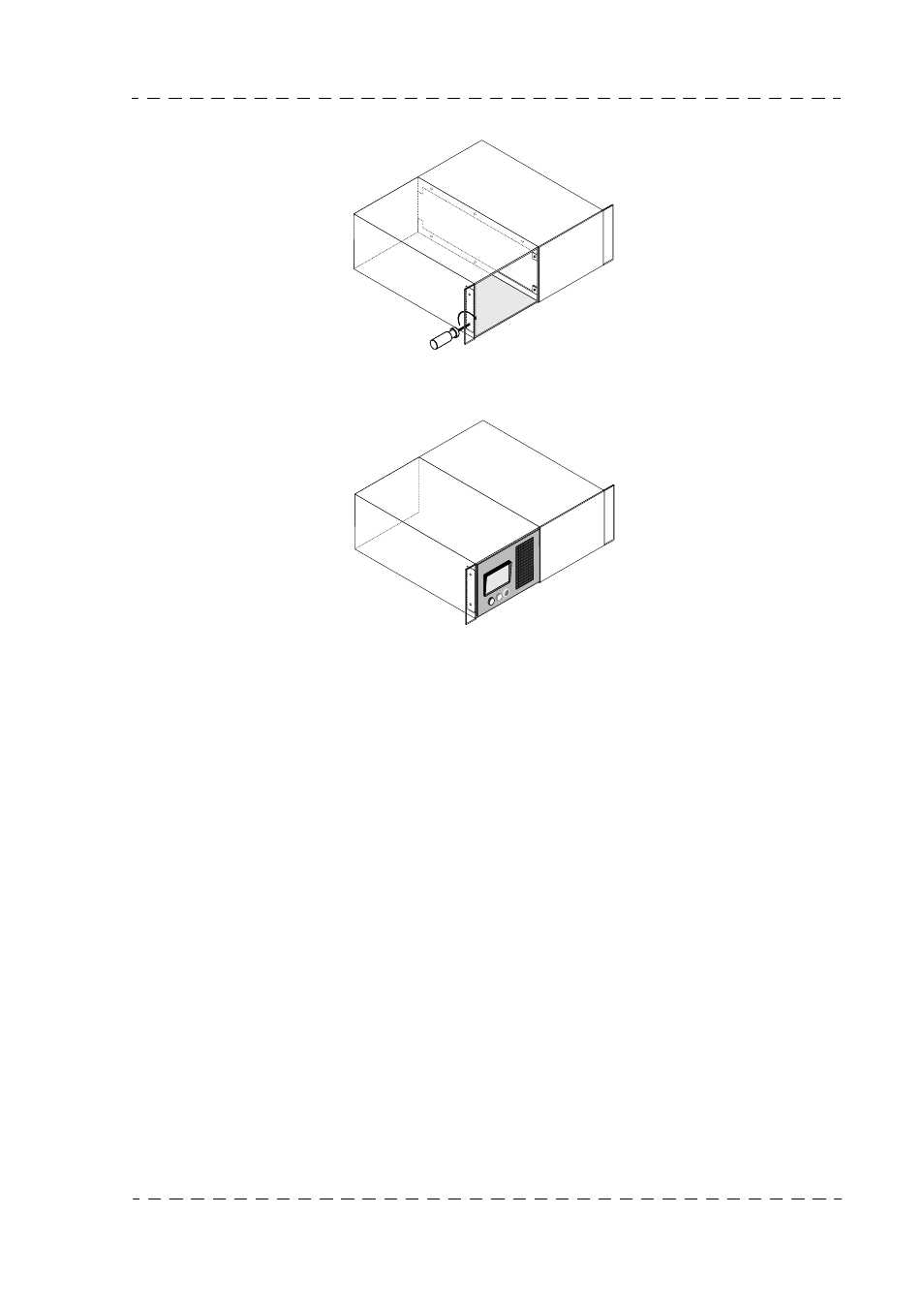
2. Couple the accessory rack to the RH side of the CCU DT500, with the lugs located
at the front of the CCU DT500.
3. Remove the power supply unit by unscrewing the 3 attaching screws.
4. Tighten the six 4 mm dia. screws using the screwdriver from inside the CCU DT500
(power supply unit removed) to attach the accessory rack to the CCU DT500.
5. Place the front cover against the right-hand edge of the CCU DT500 (only one
position correct).
6. Tighten both 3 mm dia. screws using the screwdriver from the inside of the CCU
DT500 to attach the front cover.
7. Attach the RH lug of the CCU DT500 (removed in step 1) to the right of the
accessory rack.
++7
++7