Apcm, Pal encoder, Ntsc encoder – Grass Valley EFP1685 Manuel d'utilisation
Page 173: Apcm version 0
Chapter 3 - 1685/1686 Channel Control Unit
173
CCU1685
THOMSON EFP1685/CCU1686
User manual
B1685902AC
September 2000
GEN
LOCK
REMOTE
Ø
H
Ø
SC
0
Ø
SC/H
PAL
ENCODER
CHROMA
LEVEL
¸
NTSC
ENCODER
H.BLK
V.BLK
19H
2OH
21H
ON AIR
1
2
STATUS
CAM BUSY
RCP MCP
APCM
ON LINE
MCP
CCU
NUMBER
AUX
RCP
1
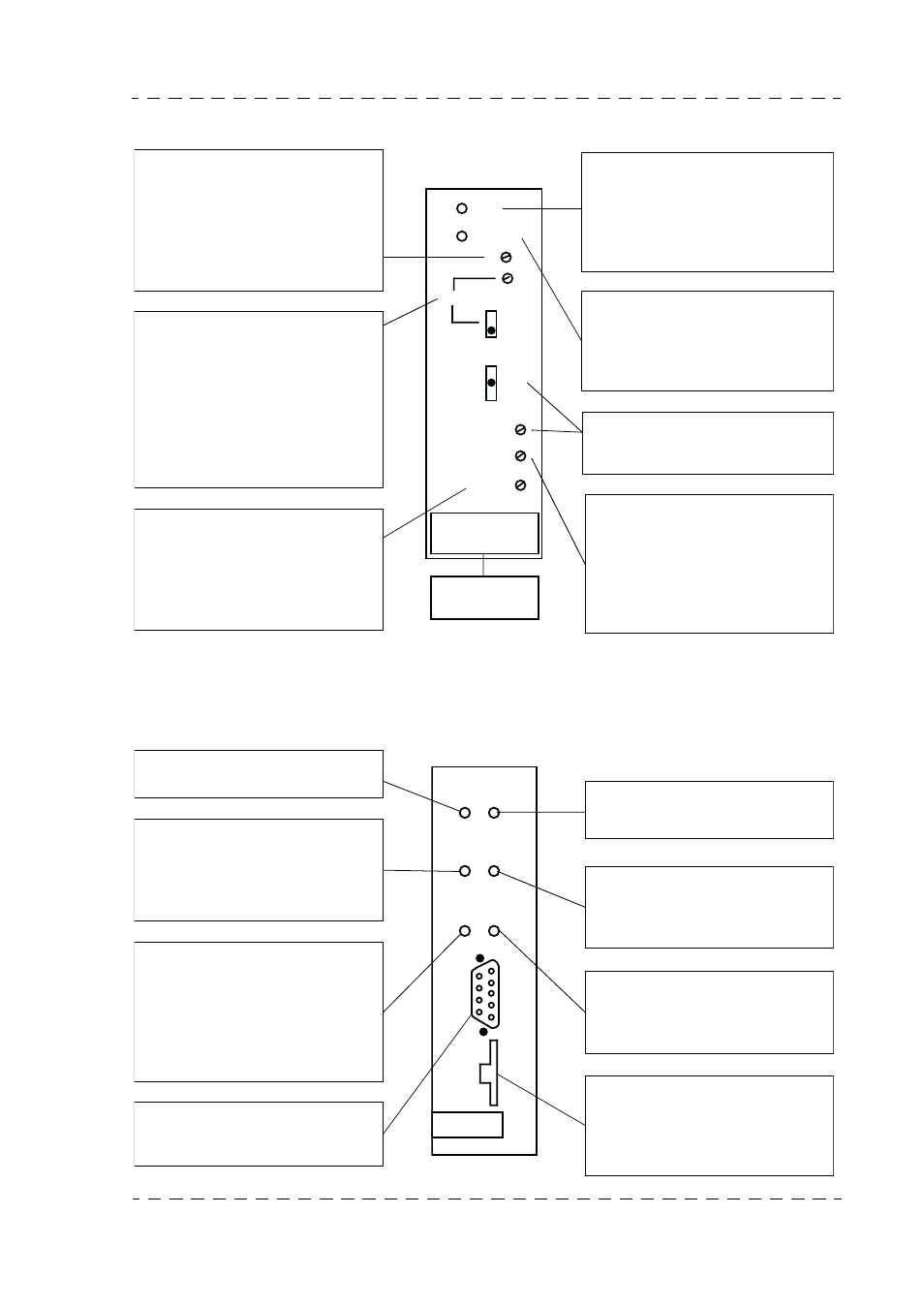
This setting ØH - horizontal phase
- advances or delays (with respect
to GEN LOCK input) the equip-
ment sync generator so that the
camera channel has the same
phase as the other video sources
at the video mixer input.
This setting ØSc (continuous set-
ting and 0/
Π switching) phase-
shifts (with respect to the GEN
LOCK input) the equipment sub-
carrier (in PAL or NTSC only) so
that the camera chain has the
same phase and sub-carrier as
other video sources at the video
mixer input.
This indicator light indicates that
the equipment sync generator (in
the channel control unit) is slaved
to the external reference signal ap-
plied to the back of the channel
control unit (GEN LOCK IN).
This red indicator light indicates
that the horizontal phase setting
and the sub-carrier phase setting
(in PAL or NTSC) are offset. This
light should be off.
For NTSC standard width adjuste-
ment of vertical blanking (V.BLK)
and horizontal blanking (H.BLK).
This setting varies the level of the
sub-carrier on the encoded out-
puts, on the rear of the channel
control unit, so that the amplitude
of the sub-carrier of the encoded
signal is correct at the mixer input.
ØSc/H adjusts the phase between
the sub-carrier and the horizontal
sync signal. If the equipment is
not servo controlled by an external
reference signal (no video on GEN
LOCK input on the back of the
Channel Control Unit).
This red light indicates that the
equipment is on the main antenna.
This red indicator light, which is
normally off, indicates a remote
control transmission fault between
the channel and camera, or the ca-
mera and channel.
This green indicator light is lit
when at least one control panel is
connected to the Channel Control
Unit.
This light flashes to indicate that
several control panels have the
same address (conflict).
Remote control console connec-
tion receptacle (provided for main-
tenance operations).
This yellow indicator light indicates
that the equipment is on the se-
condary antenna.
Flashing of this yellow light indica-
tes dialogue between the Channel
Control Unit and the control pa-
nel(s).
This green indicator light lights
when the Channel Control Unit is
connected as a tributary to a MCP.
Thumbwheel used to define the
CCU number seen and displayed
by the centralized system and the
test monitor PM.
APCM Version 0