10 - selection of digital video in test, 1 - selector switch rc1 is on operating position, 10 -selection of digital video in test – Grass Valley EFP1685 Manuel d'utilisation
Page 157
157
Selection of Digital video in test
THOMSON EFP1685 / CCU1686
User manual
B1685902AC
September 2000
2.10 -SELECTION OF DIGITAL VIDEO IN TEST
NOTE : In operation, RC1 must be set to position F.
The "4.2.2 ENCODER" board is fitted with a selector switch RC1 used:
• to select the source present on the serial digital output,
or
• to perform certain modifications on the signal on the serial digital output.
2.10.1 - Signal available on digital output, depending on the control
panel "BARS" and "PM" controls
2.10.1.1 - Selector switch RC1 is on OPERATING POSITION
Selector switch RC1 is on F
The signal depend:
• of the video selected (picture, sawtooth, or bars by the BARS key),
• of the video PM selected (SETTING CCU, SETTING key).
1st case: the control panel is on image, and whatever the selection of "PM": DIGITAL
OUTPUT = CAMERA VIDEO.
2nd case: the control panel is on "BARS PATTERN" and if "PM" is other than "ENC":
DIGITAL OUTPUT = CAMERA BAR PATTERN.
3rd case: the control panel is on "BAR PATTERN" and if "PM" is equal to "ENC":
DIGITAL OUTPUT = 100% SYNTHETIC BAR PATTERN (generated by the digital
encoder).
4th case: the control panel is on "TEST" and if "PM" is other than "ENC": DIGITAL
OUTPUT = CAMERA TEST SIGNAL.
5th case: the control panel is on "TEST" and if "PM" equal to "ENC": DIGITAL
OUTPUT = DIGITAL TEST SAWTOOTH (generated by digital encoder).
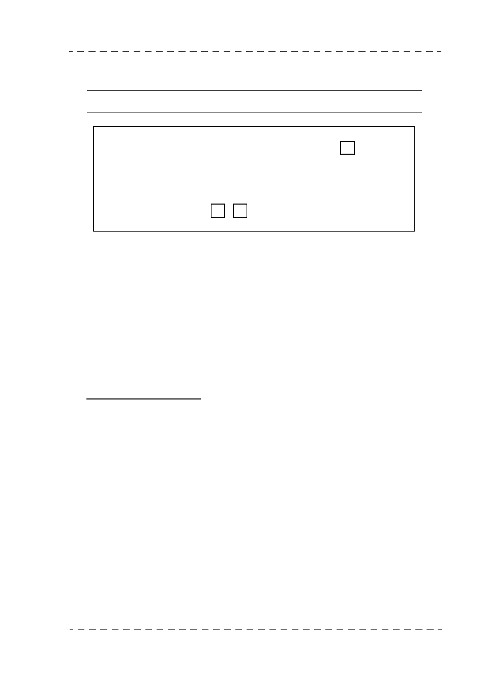
"ENC 4.2.2" PCB (CCU)
Front
panel
RC1
RC3
RC4