Grass Valley EFP1685 Manuel d'utilisation
Page 171
Chapter 3 - 1685/1686 Channel Control Unit
171
CCU1685
THOMSON EFP1685/CCU1686
User manual
B1685902AC
September 2000
ENG
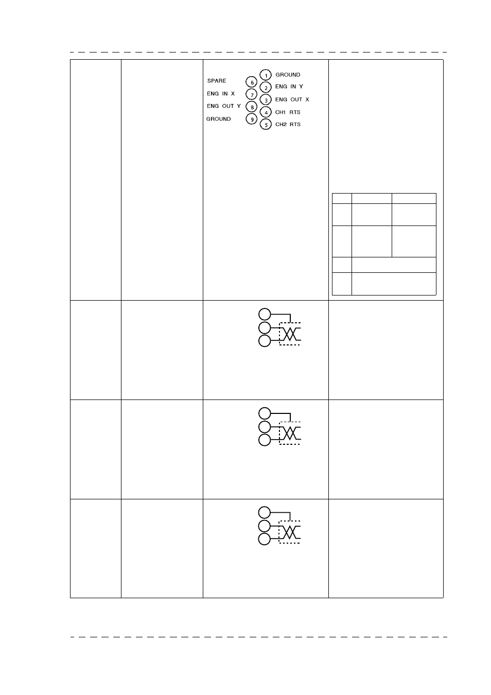
Intercom Audio
Input/Output
between Camera-
man and Technical
control room.
Depending on the position of
the straps on the "INTER-
COM" board, the intercom
link with the control room
can be a 2-wire or 4-wire
link.
The audio input and output
levels specified are 0 dB.
However it is possible to
change these levels.
Refer to chapter 2 "Installa-
tion".
Socket Type: HE501F09KS3E
P/N: T9000678
Plug
Type: HE501N09AS
P/N: 99.027.194
MIC 1
OUT
Audio Output from
Camera Mic.
The output level specified is
0 dB; however, it is possible
to change this level value.
Refer to chapter 2, "Installa-
tion".
Socket Type: NC3MK-V
P/N: T1002568
Plug
Type: XLR-3-11C
P/N: 91.355.160
MIC 2
OUT
Audio Output from
Mic connected to
CA85.
The specified audio output
level is 0 dB. However, it is
possible to change this level
value.
Refer to chapter 2 "Installa-
tion".
Socket Type: NC3MK-V
P/N: T1002568
Plug
Type: XLR-3-11C
P/N: 91.355.160
PGM IN
PROGRAM Sound
Input.
Normally the equipment is
set to receive a 0 dB level
signal. However, it is possi-
ble to adapt the equipment to
signals of other levels.
Refer to chapter 2 "Installa-
tion".
Socket Type: NC3FK-V
P/N: T1002569
Plug
Type: XLR-3-12C
P/N: 91.355.162
No
4-WIRE
2-WIRE
3 - 8
To control
room
Not
connected
2 - 7
From
control
To and from
control
room
4
Producer’s RTS channel
5
Technical room
RTS channel
room
1
2
3
(X)
GND
(Y)
1
2
3
(X)
GND
(Y)
1
2
3
(X)
GND
(Y)