2 - selector switch rc1 is on test position – Grass Valley EFP1685 Manuel d'utilisation
Page 158
158
Selection of Digital video in test
B1685902AC
September 2000
THOMSON EFP1685 / CCU1686
User manual
2.10.1.2 - Selector switch RC1 is on TEST POSITION
Selector switch RC1 is on a position other than F
RC1 is on E: DIGITAL OUTPUT = WHITE (generated by digital encoder), no matter
what is selected on the OCP.
RC1 is on D: DIGITAL OUTPUT = 100% SYNTHETIC TEST PATTERN (generated
by digital encoder), no matter what is selected on the OCP.
RC1 is on C: DIGITAL OUTPUT = DIGITAL TEST SAWTOOTH (generated by
digital encoder), no matter what is selected on the OCP.
RC1 on in B: DIGITAL OUTPUT = PULSES FOR CHECKING DIGITAL OUTPUT
PHASE (generated by digital encoder), no matter what is selected on the OCP.
RC1 is on A: DIGITAL OUTPUT = BLACK (generated by digital encoder), no matter
what is selected on the OCP.
RC1 on 9: DIGITAL OUTPUT = SIGNAL SELECTED AT CONTROL PANEL
WITH Y COMPONENT AT BLACK.
RC1 is on 8: DIGITAL OUTPUT = SIGNAL SELECTED AT CONTROL PANEL
WITH CR AND CB COMPONENTS AT BLACK.
RC1 is on 7: DIGITAL OUTPUT = SIGNAL SELECTED AT CONTROL PANEL
WITH CR COMPONENT AT BLACK.
RC1 is on 6: DIGITAL OUTPUT = SIGNAL SELECTED AT CONTROL PANEL
WITH CB COMPONENT AT BLACK.
NOTE : Positions 0, 1, 2, 3, 4 and 5 of selector switch RC1 are not used.
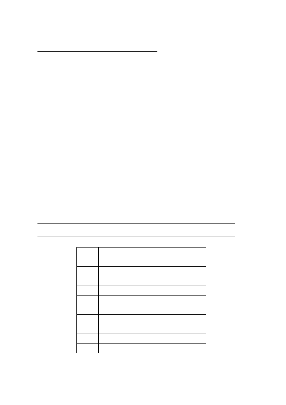
Table showing digital outputs as function of RC1
F
CAMERA
E
DIGITAL WHITE
D
100% DIGITAL BARS
C
DIGITAL TEST SAWTOOTH
B
DIGITAL PULSE
A
DIGITAL MASTER BLACK
9
CR/CB (Black on Y) of video selected
8
Y (Black on CR/CB) of video selected
7
Y + CB (Black on CR) of video selected
6
Y + CR (Black on CB) of video selected
0 to 5
NOT USED