Apcm version 1 – Grass Valley EFP1685 Manuel d'utilisation
Page 174
174
Chapter 3 - 1685/1686 Channel Control Unit
CCU1685
B1685902AC
September 2000
THOMSON EFP1685/CCU1686
User manual
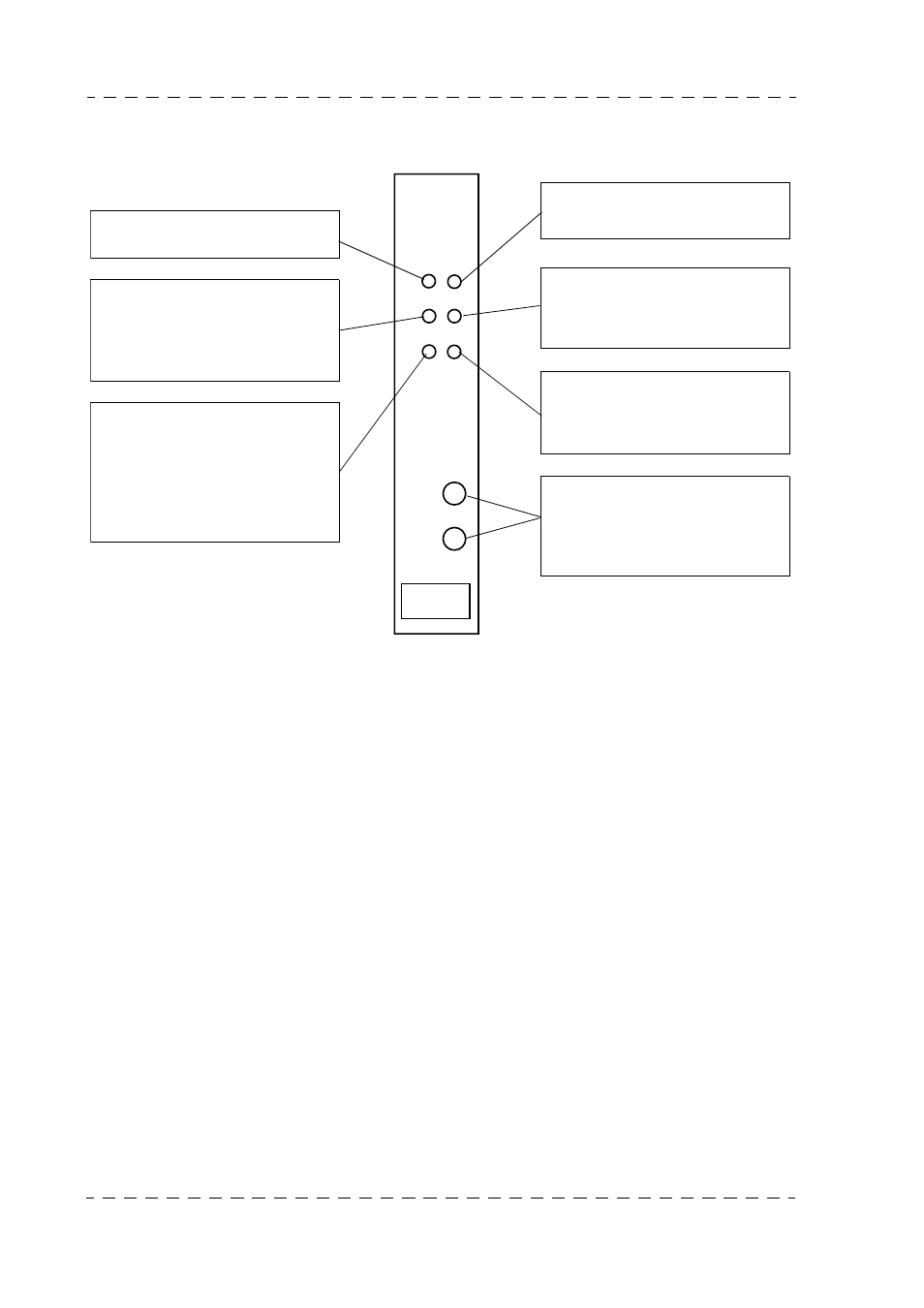
APCM
ON AIR
STATUS
ON LINE
1
2
CAM BUSY
RCP
MCP
NUMBER
MCP
This red light indicates that the
equipment is on the main antenna.
This red indicator light, which is
normally off, indicates a remote
control transmission fault between
the channel and camera, or the ca-
mera and channel.
This green indicator light is lit
when at least one control panel is
connected to the Channel Control
Unit.
This light flashes to indicate that
several control panels have the
same address (conflict).
This yellow indicator light indicates
that the equipment is on the se-
condary antenna.
Flashing of this yellow light indica-
tes dialogue between the Channel
Control Unit and the control pa-
nel(s).
This green indicator light lights
when the Channel Control Unit is
connected as a tributary to a MCP.
Thumbwheels used to define the
CCU number seen and displayed
by the centralized system and the
test monitor PM. See Chapter 2 -
"Installation".
APCM Version 1