5 - video "mix" generation – Grass Valley EFP1685 Manuel d'utilisation
Page 148
148
Video
B1685902AC
September 2000
THOMSON EFP1685 / CCU1686
User manual
2.4.4 - PAL or NTSC synchronization signals calibrate (VIDEO PIP
PCB)
Set switches S13, S15, S14 on the PIP video board to the appropriate position.
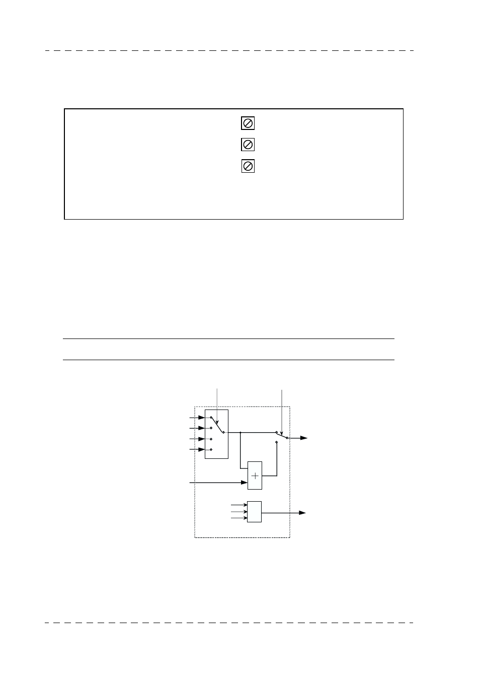
2.4.5 - Video "MIX" generation
The "MIX" video is a test signal for the Cameraman, resulting from addition of the "Y"
luminance signal to the "EXT.VIDEO" return signal, selected by the switches on the
bottom lefthand side of camera adapter CA85.
This is substituted for the "EXT.VIDEO" return signal.
NOTE : The Y signal must be phase aligned on installation.
2.4.6 - "EXT SELECT" switch on CA lefthand side control panel
This switch is used to select one "return" video input out of the 4 available at the input to
the Channel Control Unit.
Front
panel
"VIDEO PIP" PCB (CCU)
S13
S15
S14
RET VIDEO
or
MIX VIDEO
TO CAM
INFO
MIX VIDEO
FROM CAM
SELECT
RET VIDEO
FROM CAM
RET 1
RET 2
RET 3
RET 4
VIDEO
MIX IN
FROM
REAR PANEL
"VIDEO" PCB
VIDEO
MIX OUT
R
G
B
FROM CAM
Y