Grass Valley EFP1685 Manuel d'utilisation
Page 140
140
Audio
B1685902AC
September 2000
THOMSON EFP1685 / CCU1686
User manual
INTERCOM2) which are located on the Channel Control Unit "STEREO INTERCOM"
board.
NOTE : When the output level is + 12 dB, make sure that the load impedance is
greater than 5 kOhms.
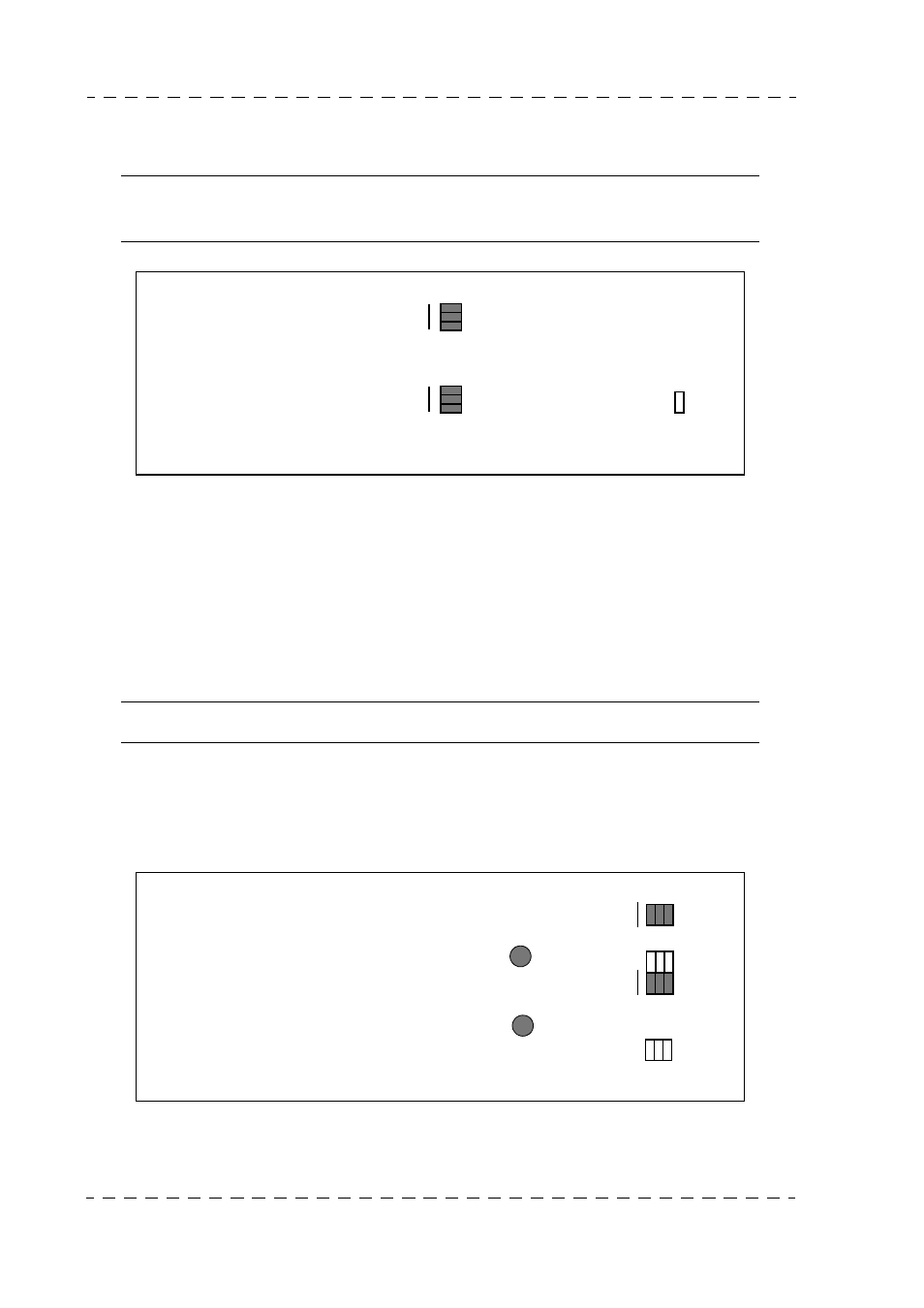
CAM to PROD links type
If the CCU to Control Room forward and return links are individualised (2 screened
symmetrical twins), each of switches S02, S03 and S04 on the "STEREO INTERCOM"
board of the Channel Control Unit must be set to the 4W position.
For a common forward-return link over 1 screened twin, set the switches to 2W. It may
then be necessary to readjust R9 "Cameraman Sound return cancellation" if the Came-
raman is hindered by his microphone sound return.
NOTA : In all cases, match the links using a load impedance of 600 Ohms.
CAM to ENG links type
Proceed as above for switches S08, S09, S10 and the "Cameraman sound return" potentio-
meter R01.
"STEREO INTERCOM" PCB (CCU)
Front
panel
+ 12 dB
OUT + 6 E12
0 E11
- 6 E10
+ 12 dB
OUT + 6 E09
0 E08
- 6 E07
E13
ENG + PROD
"STEREO INTERCOM" PCB (CCU)
Front
panel
ENG
4 W
2 W
S10
R01
PROD
4 W
2 W
S04
S02 S03
R09