2 - intercom and "program return" sound, 1 - cameraman’s intercom, 1 - cameraman’s links to prod and eng – Grass Valley EFP1685 Manuel d'utilisation
Page 138: A - microphone type
138
Audio
B1685902AC
September 2000
THOMSON EFP1685 / CCU1686
User manual
adjustment of the output level of the camera microphone is obtained via potentiometer R02
located on this board. Fine adjustment of the output level of the CA85 microphone is
obtained via potentiometer R08.
2.3.2 - Intercom and "PROGRAM RETURN" sound
Comments concerning terminology:
• "CAM" means Cameraman’s microphone,
• "ENG" means technical control room commands (engineer),
• "PROD" means producer commands,
• "PROG" means program return sound,
• "CCU" means Channel Control Unit operator’s microphone.
2.3.2.1 - Cameraman’s intercom
2.3.2.1.1 - Cameraman’s links to PROD and ENG
a - Microphone type
Depending on the type of microphone used, each of switches S11, S12 and S13 on the
"AUDIO CA85" board of the CA must be set to the ELECTRET (electrostatic headset) or
DYNAMIC (electrodynamic headset) position.
When set to ELECTRET, the CA provides + 9 V to the microphone via the headset-micro-
phone connector. This power supply is backed up when the camera head is switched off. In
this case, the microphone sensitivity can be adjusted using potentiometer R04 on the
"AUDIO CA85" board.
The microphone output nominal level must be between - 20 and - 40 dB:
• for a level of - 20 dB, set switch S10 on this board to the - 20 dB position,
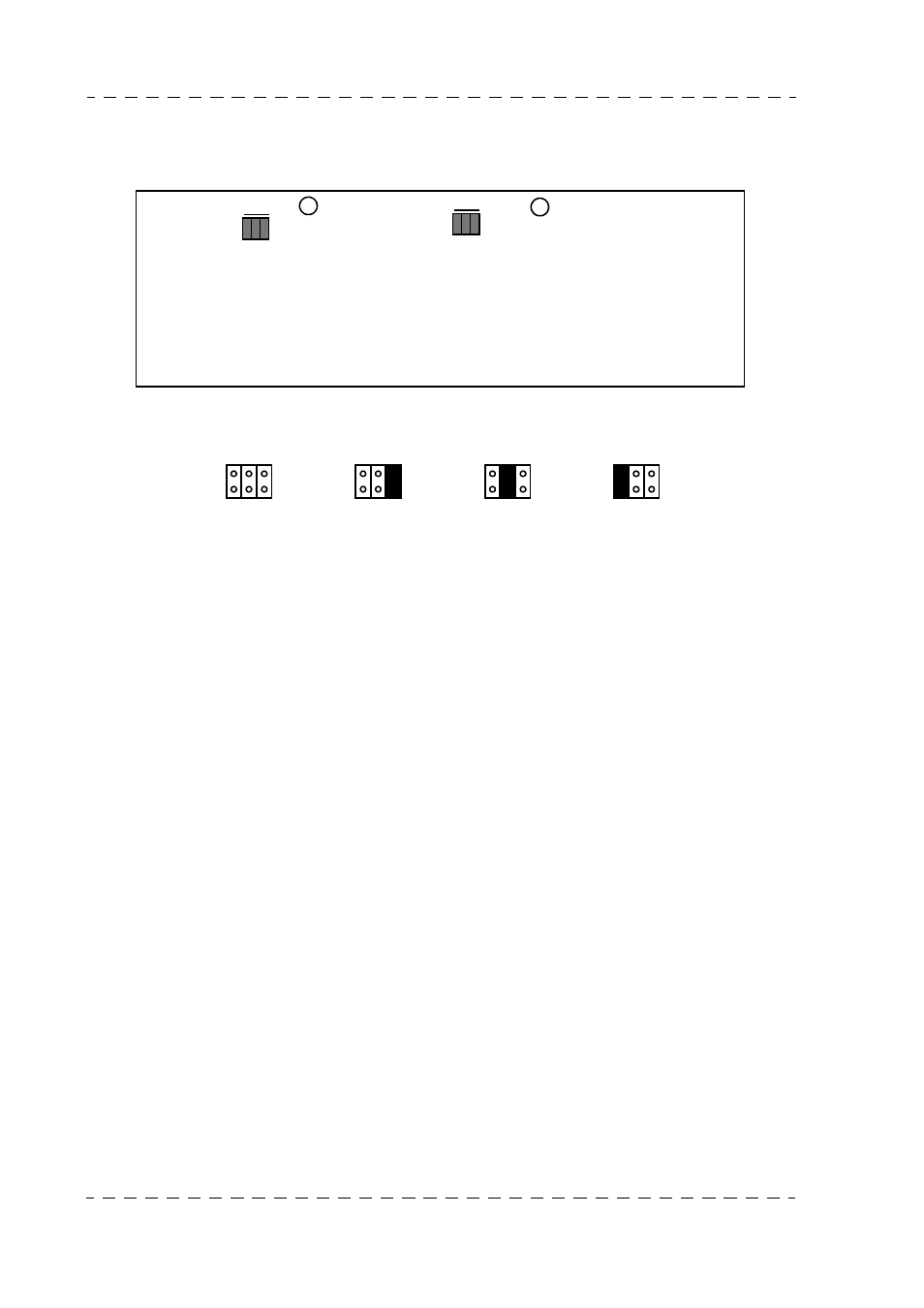
+ 12 dB
- 6 0 + 6 dB
E23 E24 E25
Front
panel
R08
MICRO2 (CA)
+ 12 dB
- 6 0 + 6 dB
E14 E15 E16
R02
MICRO1 (CAM)
"STEREO INTERCOM" PCB (CCU)
E14 E15 E16
E23 E24 E25
+ 12 dB
+ 6 dB
0 dB
- 6 dB