3 - layout of boards and connectors, 4 - removing the boards, 1 - mpu board – Grass Valley OCP 42 User Manual Manuel d'utilisation
Page 187
Advertising
Chapter 3 - OCP 42/OCP 50 Maintenance
187
Access to the various units
THOMSON OCP 42/OCP 50
User manual
B1500M24LA
September 2000
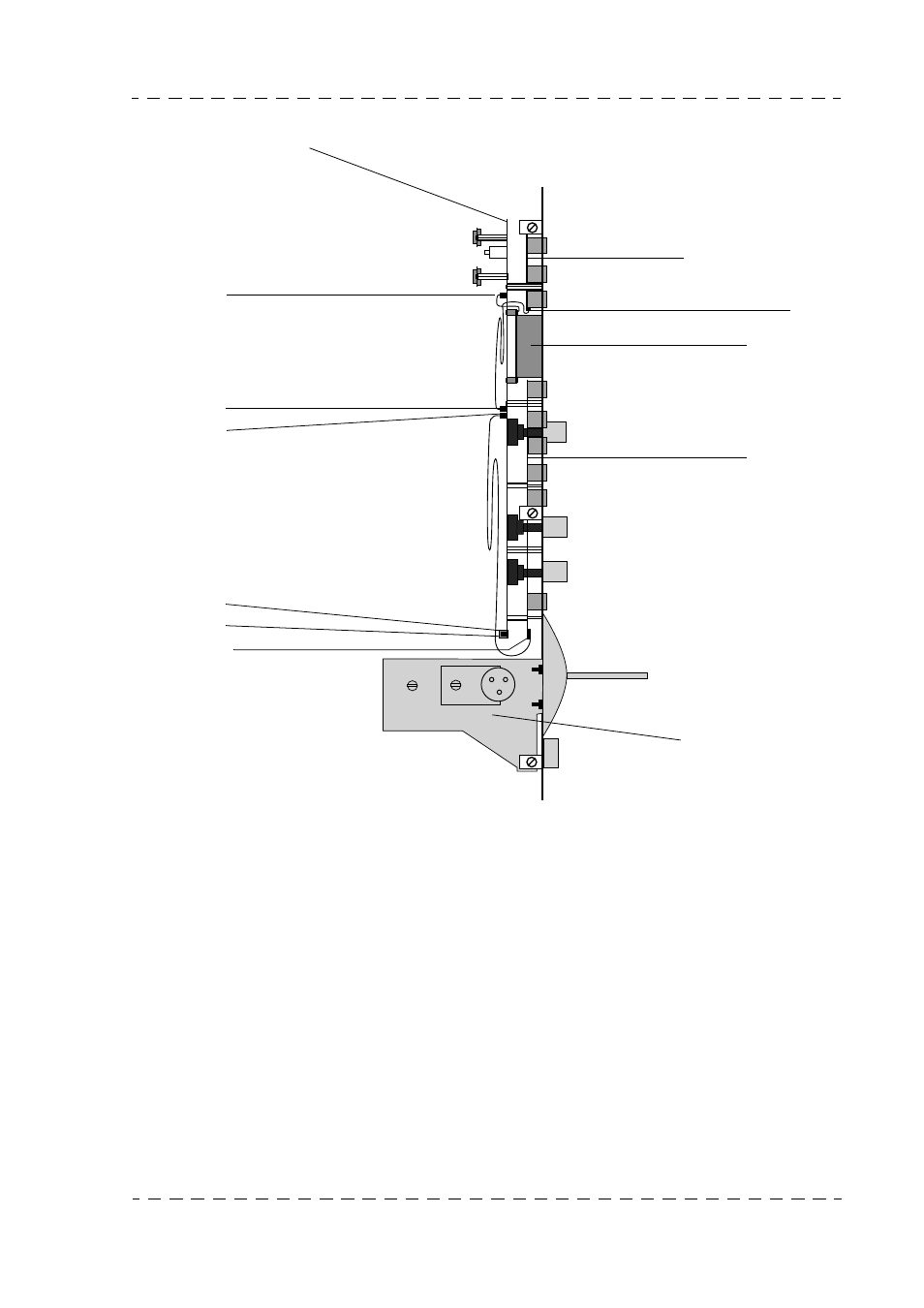
3.1.3 - Layout of boards and connectors
3.1.4 - Removing the boards
Remove the cover.
3.1.4.1 - MPU board
• Remove the 7 knobs located on the operator’s side of the panel.
• Disconnect the cables from connectors J10 and J11.
• Remove the 6 board attaching screws.
• Extract the board (the 6 soldered spacer rings remain soldered to the board).
MPU BOARD
J14
J10
J11
J111
J13
J12
TOP KEYBOARD
J110
DISPLAY
BOTTOM
KEYBOARD
MONOCONTROL
MECHANISM
Advertising
Ce manuel est liée aux produits suivants: