3 - description and connection of connectors, 1 - connector locations and functions – Grass Valley OCP 42 User Manual Manuel d'utilisation
Page 108
Advertising
108
Chapter 1 - OCP 42/OCP 50 Installation
Description and connection of connectors
B1500M24LA
September 2000
THOMSON OCP 42/OCP 50
User manual
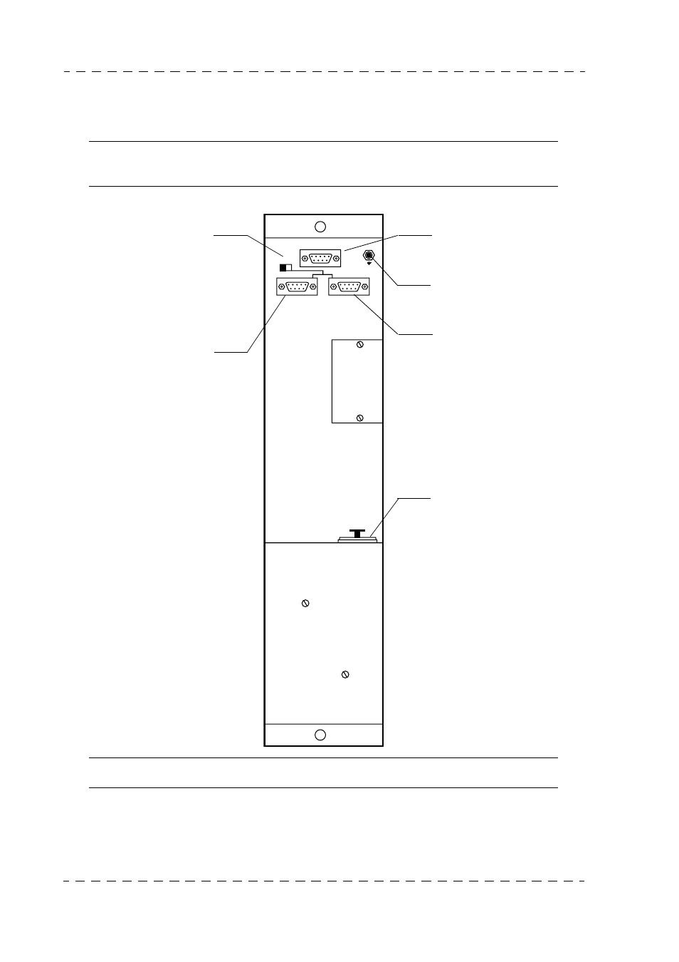
1.3 - DESCRIPTION AND CONNECTION OF CONNECTORS
1.3.1 - Connector locations and functions
Note: The OCP 50 connector functions used with a MSP (centralized system) is
described in the MCP user manual.
* NOTE:The OCP must be connecting with the ground installation
PREVIEW / AUX
LOOP 150W
CCU
LOOP
J3
DC IN 12V
J2
J1
PREVIEW input/output
Auxiliary data input
Ground connecting*
OCP/CCU or OCP/CAM
data input/output.
150 Ohms impedance on/
off. If there are no panels
connected to the LOOP
connector, this switch
should be set to 150 Ohms.
Inter-panel data input/out-
put.
Panel power supply
(10.5 to 17 Volts).
Advertising
Ce manuel est liée aux produits suivants: