2 - description of connectors – Grass Valley OCP 42 User Manual Manuel d'utilisation
Page 109
Chapter 1 - OCP 42/OCP 50 Installation
109
Description and connection of connectors
THOMSON OCP 42/OCP 50
User manual
B1500M24LA
September 2000
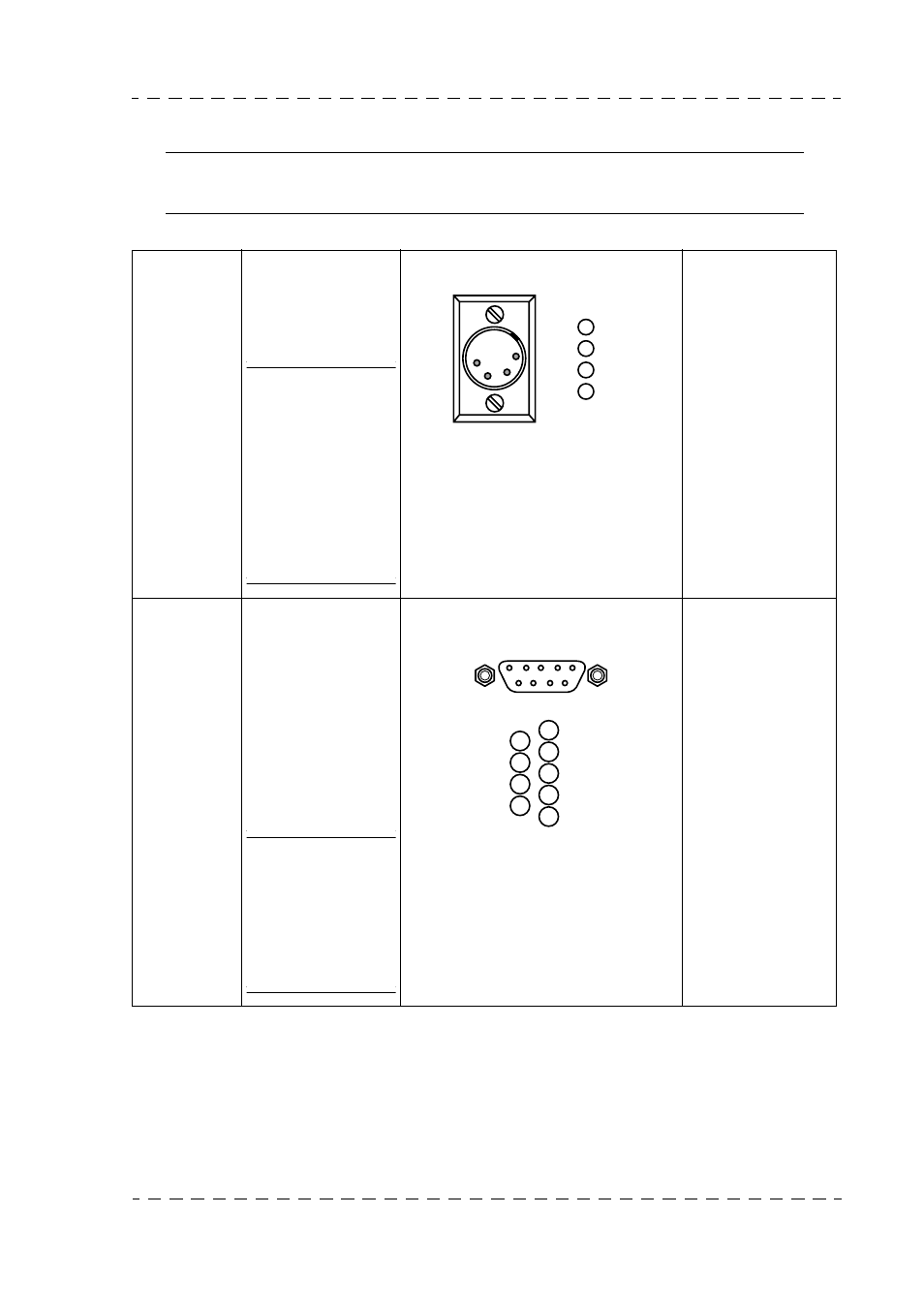
1.3.2 - Description of connectors
Note: The OCP 50 description of connector used with a MSP (centralized system) is
described in the MCP user manual.
DC IN
• DC supply input
of between 10.5
and 17 V.
Consumption:
3 Watts.
NOTE:This
receptacle
must not be
used with a
DT500 CCU.
Its power
supply must be
provided by
the CCU RCP
socket (pin 5)
Socket
Type : XLR-4-32
P/N: T1000305
Plug
Type : XLR-4-11C
P/N: 91.581.802
Refer to the panel
power supply dia-
gram below.
CCU
J1
• Data IN/OUT:
OCP/CCU or
OCP/camera.
• Power supply
input controlled
by Channel
Control Unit
(CCU 1685 -
1686- DT500)
and AUX DATA.
NOTE:This
receptacle
must be used
with a DT500
CCU for
supply the
OCP.
Socket
Type : DEP09S400T
P/N : T9001515
Plug
Type : HE501 N09 AS
P/N : 99.027.194
Set the LOOP/150
Ω
Ohms switch to
150
Ω
if there is no
panel connected to
the loop connector.
Refer to panel power
supply paragraph be-
low.
!
"
GND
1
2
3
4
+12V
!
"
#
$
%
&
'
GROUND
1
OUT A1
2
RETURN B1
3
GROUND
4
+12v CCU IN
(AUX DATA IN)
5
GROUND
6
OUT B1
7
RETURN A1
8
GROUND
9