Rear panel – Analog Way Graphic Switcher II - GSW2811 Manuel d'utilisation
Page 8
Chapter 3 : TECHNICAL DESCRIPTION (continued) GRAPHIC SWITCHER II™
PAGE 8
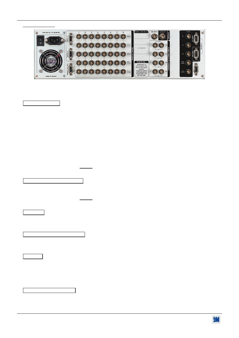
3-2. REAR PANEL
POWER CONNECTOR:
Standard IEC input connector (100-240 VAC, 50-60Hz automatic).
O / I :
Power switch (O = OFF, I = ON)
RGB / YUV INPUTS
1 to 8 :
8 x RGB/YUV inputs on 3, 4, or 5 BNC connectors. The RGB/YUV inputs can accept
both COMPUTER sources (RGBHV, RGBS, and RGsB (SOG) signals), standard
TV/VIDEO sources (YUV, RGBS (TTL), RGsB (SOG), and RGBS (analog) signals),
and HDTV SOURCES (720p & 1080i with bi-level sync only).
• RGB HV (Separate H & V Sync.) : on 5 BNC connectors.
• RGB S (Composite Sync.) : on 4 BNC connectors (R, G, B, C SYNC).
• RGsB (SOG) : on 3 BNC connectors (R, G, B).
• YUV (COMPONENT) : on 3 BNC connectors (R-Y, Y, B-Y).
• 720p & 1080i with bi-level sync : on 5 BNC connectors (RGBHV).
INPUT 2 :
2
nd
connector (HD 15 F) of the RGB/YUV INPUT 2.
INPUT 3 :
2
nd
connector (HD 15 F) of the RGB/YUV INPUT 3.
NOTE: For the INPUT #2 and #3, never connect simultaneously sources on the HD15
and on the BNC connectors.
REMOTE RS-232 & TALLY OUT
RS-232 :
Standard remote control RS-232 on DB9 F connector.
TALLY OUT :
4 tally outputs on DB9 F connector.
NOTE: This connector is also used for updating the GRAPHIC SWITCHER II
™
. (See
Chapter 8 : UPDATING THE GRAPHIC SWITCHER II™).
OPTIONAL
SDI INPUT :
Optional SDI input on BNC connector.
COMPOSITE OUTPUT :
Optional composite output on BNC connector.
COMPOSITE & S.VIDEO INPUTS
9 to 16 :
8 composite video inputs on BNC connectors.
S1 to S4 :
4 S.VIDEO (Y/C) inputs on 2 x BNC connectors.
OUTPUTS
MAIN :
MAIN output for the MAIN display device (video projector, PLASMA, data monitor)
on 3, 4, or 5 BNC connectors.
2
nd
MAIN :
Additional MAIN output on HD15 F connector.
PREVIEW :
PREVIEW output for the PREVIEW MONITOR, on HD 15 F connector.
OPTIONAL VIDEO OUTPUT Optional video output (YUV or S.VIDEO) on DB9 F connector.