Commands and responses table – Analog Way Graphic Switcher II - GSW2811 Manuel d'utilisation
Page 35
GRAPHIC SWITCHER II™ Chapter 10 : RS-232 PROGRAMMER'S GUIDE (continued)
PAGE 35
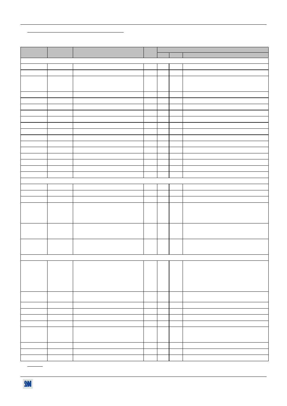
10-4. COMMANDS AND RESPONSES TABLE
The following table resumes all of the commands that are recognized as valid and the responses that will be returned to the
control device.
ASCII
RESPONSE
COMMAND
TYPE
VALUE
COMMAND
DESCRIPTION
MIN MAX
DESCRIPTION
FRONT PANEL COMMANDS
C
CH
MAIN selected input (read only).
Rd
0
21
Please see value description (next section).
c
ch
Input pre-selection (PREVIEW).
Rd/Wr
0
21
Please see value description (next section).
G
TAKE
TAKE (transition).
Rd/Wr
0
1
1 = start the transition (automatic reset at the
end of the effect duration).
0 = stop the transition (for holding effect).
Z
FRZ
FREEZE MAIN.
Rd/Wr
0
1
0 = inactive
1 = active.
z
frz
FREEZE PREVIEW.
Rd/Wr
0
1
0 = inactive
1 = active.
M
STO
STORE (MAIN).
Rd/Wr
0
1
1 = STORE action (automatic reset).
m
sto
STORE (PREVIEW).
Rd/Wr
0
1
1 = STORE action (automatic reset).
R
REC
RECALL (MAIN).
Rd/Wr
0
1
1 = RECALL action (automatic reset).
r
rec
RECALL (PREVIEW).
Rd/Wr
0
1
1 = RECALL action (automatic reset).
H
HP
Horizontal position (MAIN).
Rd/Wr
0
255
h
hp
Horizontal position (PREVIEW).
Rd/Wr
0
255
V
VP
Vertical position (MAIN).
Rd/Wr
0
255
v
vp
Vertical position (PREVIEW).
Rd/Wr
0
255
W
HW
Horizontal size (MAIN).
Rd/Wr
0
255
w
hw
Horizontal size (PREVIEW).
Rd/Wr
0
255
S
VS
Vertical size (MAIN).
Rd/Wr
0
255
s
vs
Vertical size (PREVIEW).
Rd/Wr
0
255
INPUT COMMANDS
PC
PCH
Input selection for adjustment.
Rd/Wr
0
21
Please see value description (next section).
PE
PEN
Input disabling (works with PC)
Rd/Wr
0
1
0 = Input disable
1 = Input enable.
PL
PLD
H sync load selection (works with PC). Rd/Wr
0
1
0 = Hi-Z load
1 = 75Ω load.
PR
PRGB
RGB input type selection (works with
PC command).
Rd/Wr
0
6
0 = SDTV YUV
4 = computer (SOG)
1 = SDTV RGBS (TTL) 5 = comp (HV or C.)
2 = SDTV RGsB (SOG) 6 = HDTV.
3 = SDTV RGBS (ana)
PI
PSTD
Input standard selection (works with
PC command).
Rd/Wr
0
4
0 = automatic standard detection.
1 = NTSC.
2 = PAL.
3 = SECAM
4 = Black & White.
ys
ISHR
Composite or S.VIDEO mode
selection.
Rd/Wr
0
4
0 = 8 CV
3 = 2 CV + 3 SV
1 = 6 CV + 1 SV
4 = 4 SV
2 = 4 CV + 2 SV
OUTPUT COMMANDS
F
OFMT
Output formats selection.
Rd/Wr
0
10
0 = VGA 60 Hz
6 = XGA 75 Hz
1 = SVGA 60 Hz
7 = D-ILA 4-3.
2 = XGA 60 Hz
8 = D-ILA 16/9
3 = SXGA 60 Hz
9 = 480p
4 = VGA 75 Hz
10 = 720p
5 = SVGA 75 Hz
fm
OSYN
MAIN output sync selection.
Rd/Wr
0
2
0 = Separate H &V sync. 2 =SOG
1 = Composite sync.
fp
osyn
PREVIEW output sync selection.
Rd/Wr
0
1
0 = Separate H &V sync. 1 = Composite sync.
fs
SCRN
Type of screen selection
Rd/Wr
0
1
0 = 4/3 screen
1 = 16/9 screen
pm
PAT
MAIN test pattern selection.
Rd/Wr
0
1
0 = OFF
1 = ON
pp
pat
PREVIEW test pattern selection.
Rd/Wr
0
1
0 = OFF
1 = ON
XR
REFR
Input synchronization selection.
Rd/Wr
0
21
0 = Internal rate.
17 = S.VIDEO1 rate.
1 = RGB/YUV1 rate.
21 = SDI input rate.
9 = COMPOSITE 9 rate.
ur
ADJR
Red level adjustment.
Rd/Wr
0
255
ug
ADJG
Green level adjustment.
Rd/Wr
0
255
ub
ADJB
Bleu level adjustment.
Rd/Wr
0
255
NOTE: Rd = Read only command.
Rd/Wr = Read and write command.