Analog Way Ultra VIO - VU301-IOD1 Manuel d'utilisation
Page 11
VIO1600 & ULTRA VIO
Chapter 2 : STARTING (continued)
PAGE 11
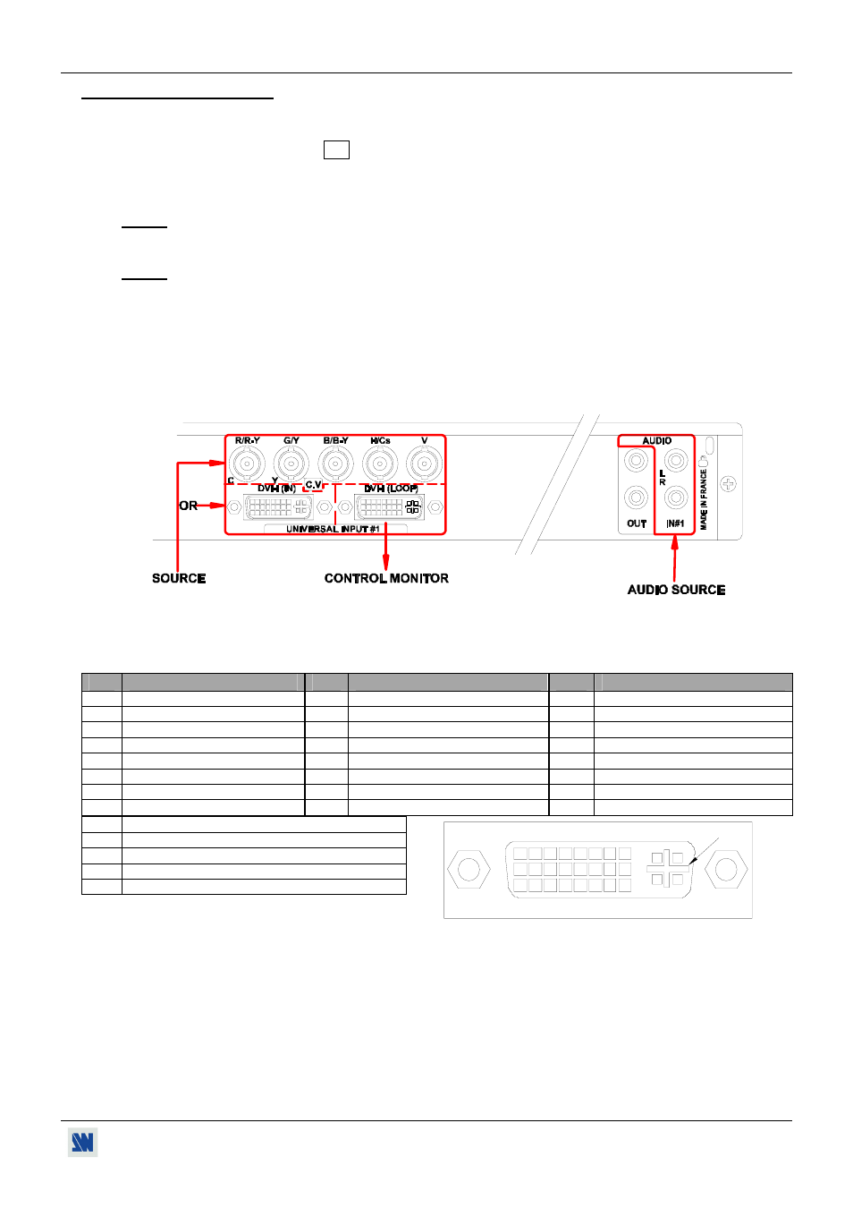
2-2. INPUT #1 DESCRIPTION
c CONNECTION:
You can connect to this input one of the following source:
• A composite video source on the C.V BNC connector or on the DVI-I (IN) connector.
• A S.VIDEO source on the Y and C BNC connectors or on the DVI-I (IN) connector.
• A Component video source on the R-Y, Y and B-Y BNC connectors or on the DVI-I (IN) connector.
• A HDTV source on the R-Y, Y and B-Y BNC connectors or on the DVI-I (IN) connector.
NOTE: The VIO1600 & ULTRA VIO accept the 720p and 1080i HDTV formats.
• A RGBS source on the R, G, B and H/Cs BNC connectors or on the DVI-I (IN) connector.
• An analog (RGBHV, RGsB, RGBS) computer source on the BNC connector or on the DVI-I (IN) connector.
NOTE: You can use the DVI / HD15 adaptor provided with the device to connect analog sources on the DVI-I (IN)
connector.
• A digital computer source on the DVI-I (IN) connector.
d LOOP-THROUGH:
You can connect a control monitor to the DVI-I (LOOP) connector. This connector can be used as well with analog
sources connected to the BNC inputs using the DVI / HD15 adaptor provided with the VIO1600/ULTRA VIO.
e INPUT #1 CONNECTION DIAGRAM:
f DVI-I PIN ASSIGNMENT:
The three DVI-I female connectors of the VIO1600/ULTRA VIO can be used with digital signals as well as analog
signals. The table hereafter explain the pin assignment of these connectors.
Pin Function
Pin Function
Pin
Function
1
TMDS Data 2-
9
TMDS Data 1-
17
TMDS Data 0-
2
TMDS Data 2+
10
TMDS Data 1+
18
TMDS Data 0+
3
TMDS Data 2 Shield
11
TMDS Data 1 Shield
19
TMDS Data 0 Shield
4
Not used.
12
Not used.
20
Not used.
5
Not used.
13
Not used.
21
Not used.
6
DDC Clock
14
+ 5V (Power)
22
TMDS Clock Shield
7
DDC Data
15
Ground for (+5V)
23
TMDS Clock+
8
Analog Vertical Sync.
16
Hot plug detect.
24
TMDS Clock-
C1
Analog Red video (or Cr / Pr or C)
C2
Analog Green Video (or Y or composite video)
C3
Analog Bleu Video (or Cb / Pb)
C4
Analog Horizontal Sync (or composite sync)
C5
Analog Common Ground Return
DDC = Display Data Channel.
TMDS = Transition Minimized Differential Signal.
g AUDIO SOURCE:
You can also connect an AUDIO stereo source on 2xRCA connectors.
8
1
9
16
24
17
C1 C2
C3 C4
C5