Limitorque actuation systems, Flow control division, Figure 6.1 : actionneur standard / triphasé – Flowserve LY Series Manuel d'utilisation
Page 30: Vanne présentée en position totalement ouverte, Moteur triphasé, Potentiomètre (vers la gauche) (vers la droite)
6-2
Installation et maintenance des LY 1001, LY 2001 et LY 300
FCD LMFIM1501-00
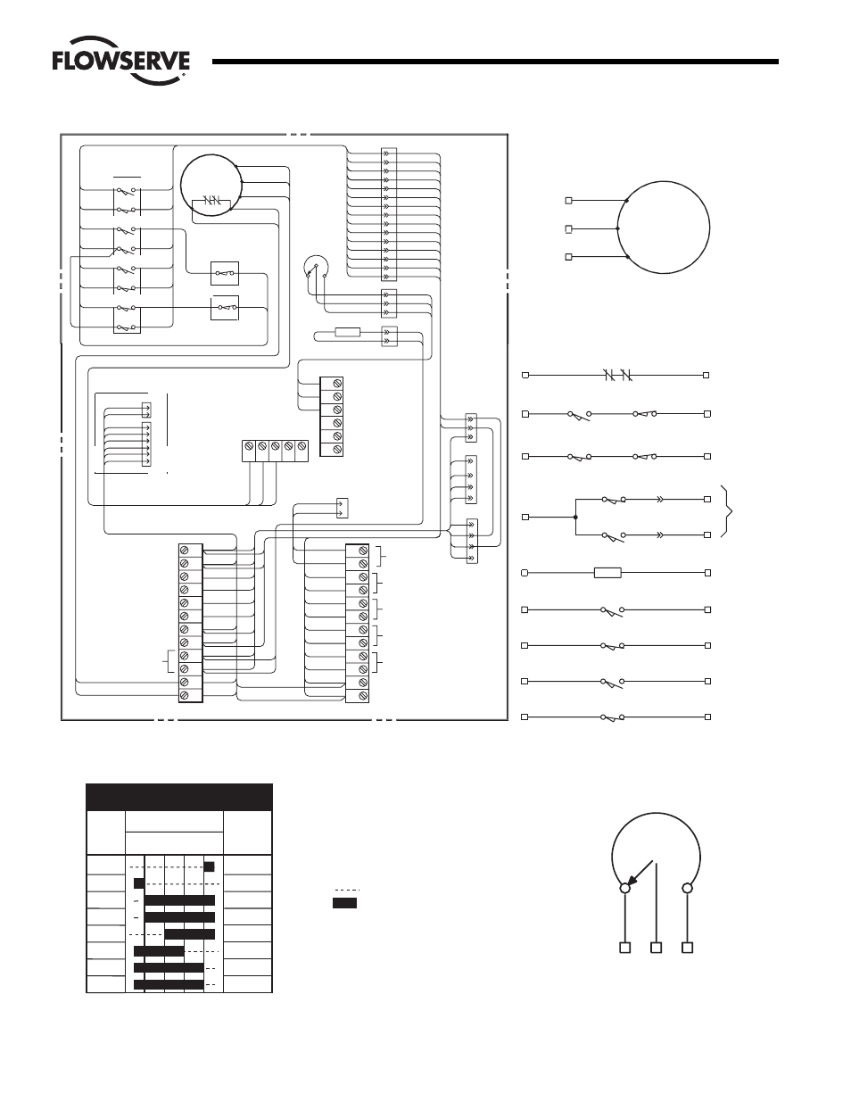
Figure 6.1 : actionneur standard / triphasé
BLU
YEL
BRN
ORG
GRY
PNK
HTR
CLOSE
OPEN
TS18
BLU
/RED
BLU/BLK
TS17
YEL/RED
YEL/BLK
RED
YEL/RED
ORG
BLK
YEL
PUR
BRN
GRN
PNK
BLK
BLU/RED
BLU
LIMIT SWITCH
BOTTOM
LS7
LS4
LS8
LS5
LS9
LS6
BLU/WH T
RED/BLK
LS3
LS2
TO P
TORQU E
SWITCHES
PUR/WHT
YEL/WHT
PNK
P2
T2
TH.OL
T1
(P)
(P)
P1
ORG
PUR
BRN
YEL/BLK
BLU/BLK
PUR/WHT
RED/BLK
YEL/WHT
BLU/WH T
PUR
P2
BLK
WHT
BLK
P1
BLK/WHT
RED/WHT
OPEN INDICATION
CLOSE INDICATION
OPEN CIRCUIT
CLOSE CIRCUIT
WHT
BLK/WHT
OPEN/C LOSE IND. COM
HEATER
T3
Moteur t riphas é
BLK
BRN
RED
POT
4
5
6
7
8
9
1
2
3
1
2
3
4
1
2
3
4
1
2
3
4
5
6
7
8
9
10
11
12
16
17
18
19
20
21
22
23
OPEN CIRCUIT
CLOSE CIRCUIT
1
2
3
15
13
24
14
10
11
12
13
14
15
2
1
SPARE
LIMIT
SWITCH#2
SPARE
LIMIT
SWITCH#3
T1
T2
T3
SPARE
LIMIT
SWITCH#6
SPARE
LIMIT
SWITCH#7
THERMAL OVERLOAD
1
2
1
2
3
4
5
6
1
2
TO MOTOR
POWER
SOURCE
FOR SIGNAL
CONVE RTER
WHEN SUPPLIED
PLUGS FOR
INTEGRAL
STARTER
28
29
30
27
25
26
POT (CCW)
POT (SWEEPER)
POT (CW)
1
2
3
PUR/WHT
RED/BLK
BRN
ORG
PUR
BUTTON S
AUX.
TERM.
LIGHTS
BLK
BLU
YEL
GRN
RED
WH
T
BRN
GRY
PNK
ORG
BLU/WH T
YEL/WHT
BLK
GRN
YEL/BLK
BLU
BLU/BLK
BLK
GRN
BLU
YEL/BLK
BLU/BLK
YEL
YEL
RED
RED
PNK
PUR
BLK
WH
T
WH
T
BLK
BLK
PUR/WHT
YEL/WHT
RED/BLK
BLU/WH T
PNK
PUR
BRN
ORG
YEL
BLU
BLK/WHT
BLU/BLK
YEL/BLK
PUR
BLK
WHT
BLK/WHT
RED/WHT
BRN
RED
BLK
BLK
BRN
RED
BR
N
RE
D
BL
K
Développement du contact de
l’interrupteur de fin de course
Contact de
l’interrupteur
de fin de
course
2
3
4
5
6
7
8
9
Position de la vanne
Ouverture
Fermeture
totale
FONCTION
SPARE
SPARE
OPEN LIMIT
IND LIGHT
INDICATION
INDICATION
CLOSED LIMIT
IND LIGHT
Vanne présentée en position totalement ouverte
LEGENDE
TH. OL - Contacts de surcharge thermique
HTR - Calorifère
Potentiomètre - Transmetteur à fil
TS18 — Le limiteur de couple d’ouverture
interrompt le circuit de commande
en cas de surcharge mécanique
pendant l’ouverture.
TS17 — Le limiteur de couple de
fermeture interrompt le circuit
de commande en cas de surcharge
mécanique pendant la fermeture.
NOTES
1.
Contact OUVERT
2. Contact FERMÉ
3. Tous les points de déclenchement
des interrupteurs de fin de course
sont entièrement ajustables.
LS9
LS4
TS18
TS17
LS8
LS5
23
24
5
6
TH.OL
(P2)
(P1)
11
12
LS7
22
LS6
20
LS3
18
LS2
16
10
8
YELLO W
RED
YELLOW
YELLO W
BLACK
BLUE
RED
RED
GREEN
BLUE
WHITE
BLACK
PUR
ORG
PNK
BRN
YEL/WHT
BLU/WH T
PUR/WHT
RED/BLK
GRAY
PINK
HEATER
SPARE LIMIT SWITCH
SPARE LIMIT SWITCH
OPEN CIRCUIT
CLOSE CIRCUIT
THERMAL OVERLOAD S
INDICATION
BLUE
BLACK
SPARE LIMIT SWITCH
SPARE LIMIT SWITCH
BLACK
HTR
2
1
9
21
19
17
15
Moteur
triphasé
T2
T1
T3
Potentiomètre
(Vers la
gauche)
(Vers la
droite)
26
25
27
NOIR
MAR
R
O
N
R
OUG
E
totale
Flow Control Division
Limitorque Actuation Systems