Analog Way Octo-Quattro - OTR401 Manuel d'utilisation
Page 26
Chapter 8 : REMOTE CONTROL PROGRAMMER'S GUIDE (continued)
OCTO-QUATTRO™
PAGE 26
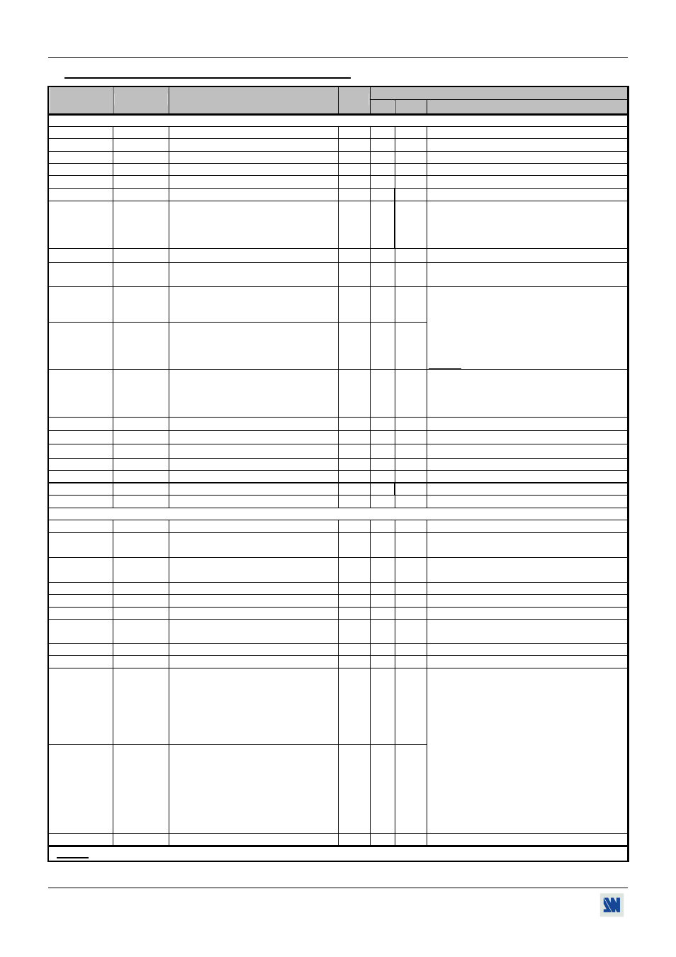
8-4. COMMANDS AND RESPONSES TABLE (continued)
VALUE
ASCII
COMMAND
RESPONSE
COMMAND
DESCRIPTION
TYPE
MIN MAX
DESCRIPTION
CONTROLS COMMANDS
xu
VERU
Device
version.
Rd
0 65535 Example: 104 = Version 1.4
xi
I Identification
number.
Rd
0 65535 Value displayed in hexadecimal in the device.
yo
OPT
Options
available.
Rd
0 65535 0 = without option.
QE
EPD
2:2 pull down correction.
Rd/Wr
0
1
0 = off
1 = auto.
yl
LOCK
Key locking.
Rd/Wr
0
1
0 = unlocks
1 = locks
yi
EISP
Auto-lock
Rd/Wr
0
1
0 = off
1 = on.
LF LFAD
Transition
mode.
Rd/Wr
0
4
0 = fade color
2 = Clean cut (from computer)
3 = Clean cut (from video)
4 = Clean cut (from all)
at
AFRA
Auto frame
Rd/Wr
0
1
0 = OFF
1 = ON
wp STBE
standby
delay
Rd/Wr
0
255
0 = OFF
1 = 1 minute
2 = 2 minutes
255 = 255 minutes
wo
MESO
ON message for the display device.
Rd/Wr
0
255
wf
MESF
OFF message for the display device.
Rd/Wr
0
255
The ON/OFF messages can be composed up to
50 bytes. Set this command to the first byte
with the wt command, then send successively
the value and the command letters for each byte
i.e: If your ON message is ABC, send:
1wt 65wo 66wo 67wo 0wo .
NOTE: 0 value = no data.
wt MCTR
ON/OFF
message
controls.
Rd/Wr
0
8
1 = set the wo command to the first byte.
2 = set the wf command to the first byte.
4 = read the ON message.
8 = read the OFF message.
ws
STDB
Standby mode
Rd/Wr
0
1
0 = standby inactive
1 = standby active.
wr
RATE
Baud rate selection to the display device Rd/Wr
0
2
0 = 9600
1 = 2400
2 = 1200 bauds.
br
BFCR
Red level adjustment of the fade.
Rd/Wr
0
255
bb
BFCB
Bleu level adjustment of the fade.
Rd/Wr
0
255
bg
BFCG
Green level adjustment of the fade.
Rd/Wr
0
255
yc
EPOS
Erase memories.
Rd/Wr
0
1
1 = erase all memories (automatic reset).
Y
FRES
DEFAULT VALUE.
Rd/Wr
0
1
1 = Default value action (automatic reset).
STATUS
COMMANDS
U
UNIT
Measures unity in kHz.
Rd
0 65535
IL ILD
This command allows to calculate the
input line frequency in Hz.
Rd
0 65535 Line frequency (in kHz) = (UNIT VALUE) ÷
(ILD VALUE).
ID IFD
This command allows to calculate the
input frame frequency in Hz.
Rd
0 65535
Frame frequency (in Hz) = (Line frequency in
Hz)
÷ (IFD VALUE).
IP
IPS
Input Sync. detection.
Rd
0
1
0 = not detected
1 = Sync. detected.
IH
IHP
Sign of the horizontal input Sync.
Rd
0
1
0 = negative
1 = positive.
IV
IVP
Sign of the vertical input Sync.
Rd
0
1
0 = negative
1 = positive.
IK
IST
Input Sync type detection.
Rd
0 3
0 = H &V.
2 = SOG.
1 = Composite (TTL). 3 = Composite (ana)
II
IIN
Interlaced signal detection.
Rd
0
1
0 = not interlaced
1 = interlaced.
IO
IOO
"Out of range" signal detection.
Rd
0
1
0 = In range
1 = Out of range.
IF
IFA
Standard input signal detection.
Rd
0 27
XF
REFF
Standard of the reference input.
Rd
0 27
0 = no signal.
1 = not compatible.
2 = NTSC (3.58/60).
3 = NTSC (4.43/60).
4 = PAL (4.43/50).
5 = PAL (4.43/60).
6 = SECAM (50Hz).
7 = B & white (50Hz).
8 = B & white (60Hz). 9 = YUV 50 Hz.
10 = YUV 60 Hz.
11 = RGB 50 Hz.
12 = RGB 60 Hz.
13 = VGA1 350L.
14 = VGA2 400L.
15 = VGA3 480L.
16 = PLASMA 42".
17 = SVGA.
18 = MAC.
19 = XGA.
20 = PLASMA 50'.
21 = MAC 21'.
22 = SXGA.
23 = UXGA.
24 = 1080i @ 50 Hz.
25 = 1080i @59.94/60.
26 = 480p @ 59.94/60. 27 = 720p @ 59.94/60.
XT
REFT
Frame frequency of the reference input Rd
0 65535 Value
in
Hz.
NOTE:
Rd/Wr = Read and write command.
Rd = Read only command.