Panasonic WJ-HD500 Manuel d'utilisation
Panasonic, Operating instructions wj-hd500
Attention! Le texte de ce document a été détectée automatiquement. Pour consulter le document original, vous pouvez utiliser le mode "Original".
Advertising
Table des MATIÈRES
Document Outline
- Panasonic
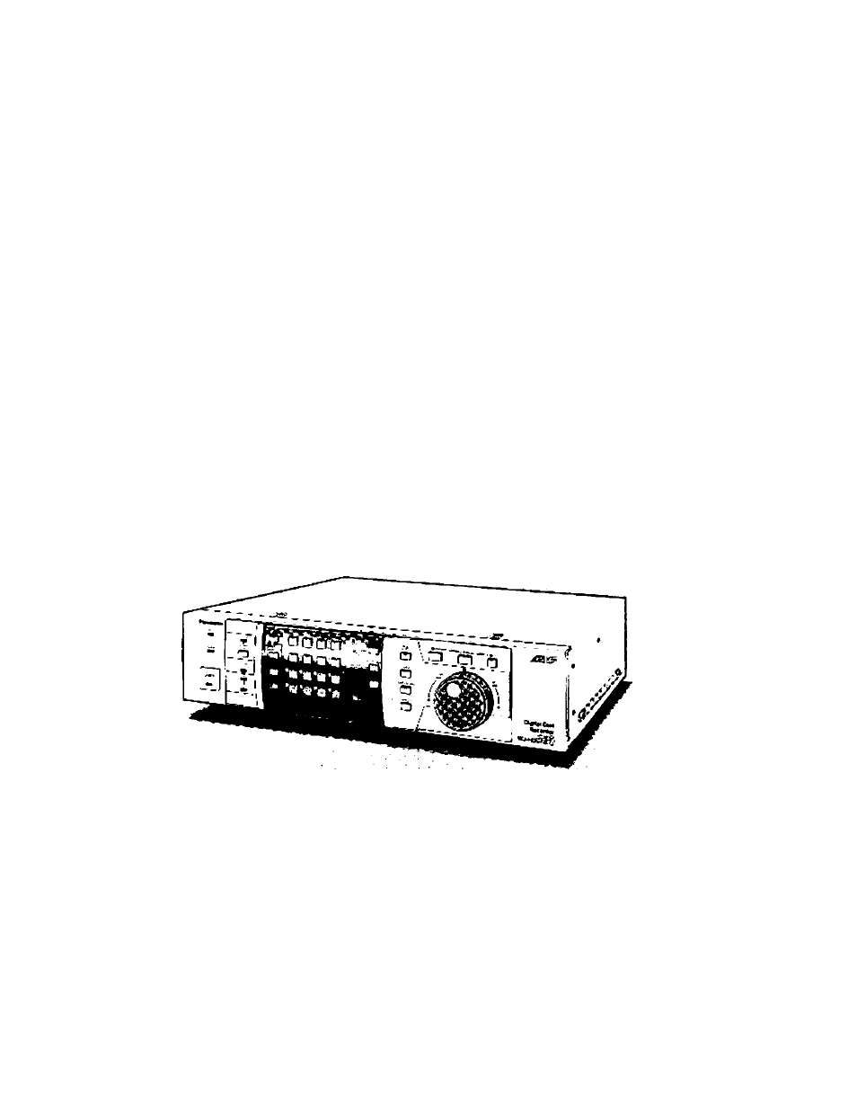
- Digital Disk Recorder
- CONTENTS
- PREFACE
- FEATURES
- PRECAUTIONS
- • Do not block the ventilation opening or slots on the cover.
- • Do not drop metallic parts through slots.
- • Do not attempt to disassemble the appliance.
- • Handle the appliance with care.
- • Do not expose the appliance to water or moisture, nor try to operate it in wet areas.
- * Do not use strong or abrasive detergents when cleaning the appliance body.
- Do not operate the appliance beyond its specified temperature, humidity or power source ratings.
- Fully charge up the backup battery.
- MAJOR OPERATING CONTROLS AND THEIR FUNCTIONS
- Front View
- (D Operate Indicator (OPERATE)
- CD Timer Indicator (TIMER)
- (D Remote Indicator (REMOTE)
- 0 Alarm Suspend Indicator (ALARM SUSPEND)
- © Alarm Reset Button (ALARM RESET)
- 0 Alarm Indicator (ALARM)
- 0 Sequence Button (SEQUENCE)
- ® Multiscreen Selection Button (MULTISCREEN SELECT)
- ® Monitor Selection Button (SPOT / MULTISCREEN)
- ® Lock Button (LOCK)
- ® Numeric Buttons (1 -16)
- ® Set Button (SET)
- ® Increment/Decrement Button {[+], 0)
- ® Recording Stop Button (REC STOP)
- ® Recording Preview Button (REC PREViEW)
- @ Index Button (INDEX)
- Group Selection Button (GROUP SELECT)
- ® Stop Button (STOP)
- ® Playback / Pause Button (PLAY/PAUSE)
- ® Record Button (REC)
- @ Jog Dial
- @ Shuttle Ring
- ® Display Button (DISPLAY)
- ^ Alarm Search Button (ALARM SEARCH)
- @ Electronic Zoom Button (EL-ZOOM)
- ® Daylight Savings Button (DAYLIGHT SAVINGS)
- @ Copy Button (COPY)
- ® Setup / Escape Button (SETUP/ESC)
- ^ Direction Buttons (T A ^
- Full Indicator (FULL)
- ® Hard Disk Drive Indicator (HDD)
- ® Multiscreen Output Connector (MULTI SCREEN OUT)
- Spot Output Connector (SPOT OUT)
- © Audio Input Connector (AUDIO IN)
- @ Audio Output Connector (AUDIO OUT)
- ® Extension Storage Port (EXT STORAGE)
- Ф Control Port (CONTROL)
- Alarm Port (ALARM)
- @ Remote Port [REMOTE (WV-CU50)]
- ® Serial Port (SERIAL)
- Signal Ground Terminal (SIGNAL GND)
- @ 10/100BASE-T Port (Optional)
- Cooling Fan
- AC Inlet Socket (AC IN)
- ® Power Switch (POWER ON/OFF)
- @ Video Output Connectors (VIDEO OUT 1-16)
- ® Video Input Connectors (VIDEO IN 1 -16)
- Copy Port (COPY)
- Mode Selector (MODE)
- Data Port (DATA)
- WV-CU50 Remote Controller
- 0 Lock Button (LOCK)
- Monitor Selection Button (SPOT/MULTISCREEN)
- 0 Multiscreen Selection Button (MULTISCREEN SELECT)
- ® Recording Preview Button (REC PREVIEW)
- ® Sequence Button (SEQUENCE)
- Ф Electronic Zoom Button (EL-ZOOM)
- ® Group Selection Button (GROUP SELECT)
- Ф Index Button (INDEX)
- Ф Alarm Search Button (ALARM SEARCH)
- Direction Buttons (▼ A ►)
- Stop Button (STOP)
- Record Button (RECORD)
- Playback / Pause Button (PLAY/PAUSE)
- JogDial
- Display Button (DISPLAY)
- ® Link Indicator (LINK)
- Shuttle Ring
- @ Recording Stop Button (REC STOP)
- Remote Port (REMOTE)
- Copy Button (COPY)
- Numeric Buttons (1 -16)
- increment / Decrement Button ((3, Q)
- Front View
- INSTALUTION
- CONNECTIONS
- POWER UP PROCEDURE
- FORMAHING THE HARD DISK
- FORMAHING THE DVD-RAM DISK
- MIRRORING FUNCTION
- DISK REMOVE
- MONITORS AND DISPLAYS
- HARD DISK and RECORDING
- SETUP MENU
- TIMER SEHING
- RECORDING SETUP
- Recording Quality Setup
- Group Setup
- ■ Recording of the Title Display
- ■ Recording of the Clock Display
- Playback Mode Setup
- ■ Hard Disk End Setup
- ■ Thumbnail Display Setup
- ■ Manual Recording Mode Setting
- ■ Alarm Recording (Manual Recording)
- Program Timer
- ■ Special Day Timer
- External Program Timer
- ■ Time Lapse Recording (Internal Timer)
- MULTIPLEXER SETUP
- ALARM SETUP
- DISPLAY SETUP
- COMMUNICATION SETUP
- SYSTEM SETUP
- CONTROLLING THE VIDEO INPUT AND MONITORS
- ALARM CONTROL FUNCTION
- RECORDING
- PLAYBACK
- TABLE DES MATIERES
- PREFACE
- CARACTERISTIQUES DOMINANTES
- MESURES DE PRECAUTION
- • Ne pas obturer les ouvertures d’aération ni les fentes du couvercle de l’appareil.
- • Ne jamais faire tomber d’objets métalliques par les fentes d’aération.
- • Ne jamais essayer de démonter l’appareil
- • Manipuler délicatement l'appareil.
- • Ne pas se servir de produits d’entretien vioients ni d’abrasifs pour nettoyer ie coffret de i’appareil.
- • Charger ia pile de sauvegarde au maximum.
- PRINCIPAUX ORGANES DE COMMANDE ET FONCTIONS
- Face avant
- (D Témoin de fonctionnement (OPERATE)
- (D Témoin de temporisateur (TIMER)
- Indicateur de commande à distance (REMOTE)
- (D Bouton de sélection de découpage multiple d’écran (MULTISCREEN SELECT)
- ® Témoin de suspension d’alarme (ALARM SUSPEND)
- Bouton de réenclenchement d’alarme (ALARM RESET)
- Bouton de sélection de moniteur vidéo (SPOT/MULTISCREEN)
- (T) Bouton de séquence (SEQUENCE)
- Bouton de verrouillage (LOCK)
- ® Pavé de touches numériques (1-16)
- © Bouton de retenue (SET)
- © Boutons de progression i de régression ((+], Q)
- ® Bouton d’arrêt d’enregistrement (REC STOP)
- ® Bouton de prévision d’enregistrement (REC PREVIEW)
- © Bouton d’index (INDEX)
- © Bouton de sélection de groupe (GROUP SELECT)
- © Bouton PLAYBACK / pause (PLAY/PAUSE)
- © Bouton d’enregistrement (REC)
- <|î) Volant de marche par impulsions
- © Bague de navette
- © Bouton d’affichage (DISPLAY)
- @ Bouton de recherche d’alarme (ALARM SEARCH)
- © Bouton de commande de zoom électronique (EL-ZOOM)
- © Bouton de réglage sur l’heure d’été (DAYLIGHT SAVINGS)
- @ Bouton de copie (COPY)
- © Bouton de configuration / d’échappement (SETUP/ESC)
- Boutons de déplacement (T A ^
- Indicateur de limite de capacité (FÜLL)
- Indicateur lecteur de disque dur (HDD)
- ® Connecteur de sortie de découpage multiple d’écran (MULTISCREEN OUT)
- © Connecteur de sortie d’observation site continue (SPOT OUT)
- © Connecteur d’entrée audio (AUDIO IN)
- ® Connecteur de sortie son (AUDIO OUT)
- ® Port de mémoire d’extensions (EXT STORAGE)
- ® Port CONTROL (CONTROL)
- CONTROL
- ALARM
- Port série (SERIAL)
- Borne de masse électrique (SIGNAL GND)
- Port 10/100BASE-T (optionnel)
- Ventilateur de refroidissement
- Prise d’entrée courant alternatif (AC IN)
- Interrupteur d’alimentation (POWER ON/OFF)
- Connecteurs de sortie vidéo (VIDEO OUT 1-16)
- Connecteurs d’entrée vidéo (VIDEO IN 1 -16)
- ® Port de copie (COPY)
- ® Sélecteur de mode (MODE)
- ® Port de données (DATA)
- Contrôleur à distance WV-CU50
- Bouton de verrouillage (LOCK)
- @ Bouton de sélection de moniteur vidéo (SPOT/MULTISCREEN)
- @ Bouton de sélection de découpage multiple d’écran (MULTISCREEN SELECT)
- ® Bouton de prévision d’enregistrement (REC PREVIEW)
- ® Bouton de séquence (SEQUENCE)
- ® Bouton de commande de zoom électronique (EL-ZOOM)
- ® Bouton de sélection de groupe (GROUP SELECT)
- @ Bouton d’index (INDEX)
- Bouton de recherche d’alarme (ALARM SEARCH)
- ® Bouton d’affichage (DISPLAY)
- ® Indicateur de lien (LINK)
- © Bouton de copie (COPY)
- Pavé de touches numériques (1-16)
- @ Boutons de progression / de régression {(+], (3)
- Boutons de déplacement (T ▲ -^ ^)
- @) Bouton d’arrêt (STOP)
- ® Bouton d’enregistrement (RECORD)
- @ Bouton de lecture / pause (PLAY/PAUSE)
- © Volant de marche par impulsions
- © Bague de navette
- @ Bouton d’arrêt d’enregistrement (REC STOP)
- © Port CONTROL à distance (REMOTE)
- Face avant
- INSTALLATION
- CONNEXIONS
- PROCEDURE DE MISE SOUS TENSION
- FORMATAGE DU DISQUE DUR
- FORMATAGE DU DISQUE DVD-RAM
- FONCTION MIROIR
- DISQUE RETIRE
- MONITEURS ET AFFICHAGES
- DISQUE DUR ET ENREGISTREMENT
- MENU DE CONFIGURATION
- CONFIGURATION DE TEMPORISATEUR
- CONFIGURATION D'ENREGISTREMENT
- ■ Configuration de qualité d'enregistrement
- Configuration de groupe
- ■ Enregistrement de l'affichage de titre
- ■ Enregistrement de l'affichage d'horloge
- ■ Configuration d'affichage de vignette
- ■ Configuration de mode de lecture
- ■ Configuration de fin de disque dur
- ■ Enregistrement d'alarme (enregistrement manuel)
- ■ Temporisateur de programme
- ■ Temporisateur de jour spécial
- ■ Temporisateur de programme externe
- ■ Enregistrement longue durée (temporisateur Interne)
- ■ Enregistrement de secours (enregistrement longue durée)
- CONFIGURATION DE MULTIPLEXEUR
- ■ Configuration de séquence (moniteur d'affichage de découpage multiple d'écran)
- ■ Configuration de séquence (moniteur d'observation site continue)
- ■ Configuration de mise sous tension (moniteur d'affichage de découpage multiple d'écran)
- ■ Configuration de mise sous tension (moniteur d'observation site continue)
- CONFIGURATION D'AURME
- ■ Alarm Configuration de port d'alarme
- ■ Configuration de remise à l'état initial automatique
- ■ Configuration de sortie d'alarme
- Configuration de sonnerie d'alarme
- Configuration d'alarme de perte vidéo
- Configuration de détecteur de mouvement vidéo
- ■ Mode d'alarme sur le moniteur d'affichage de découpage multiple d'écran
- ■ Mode d'alarme sur le moniteur d'observation site continue
- CONFIGURATION D'AFFICHAGE
- ■ Configuration de titre de caméra vidéo
- ■ Configuration d'affichage (moniteur d'affichage de découpage multiple d'écran)
- ■ Configuration d'affichage de titre (moniteur d'observation site continue)
- ■ Configuration d'affichage d'aiarme
- ■ Configuration de position d'affichage d'horloge et d'état
- ■ Configuration de position d'affichage de titre
- CONFIGURATION DE COMMUNICATION
- ■ Configuration de PS Data
- • Configuration d'adresse d'unité
- • Vitesse de transmission
- • Bit d'informations
- • Contrôle de parité
- • Bit d'arrêt
- • Temps d'attente
- • Données d'alarme
- • Configuration de numéro d'entrée (caméra vidéo)
- • Vitesse de transmission
- • Bit d'informations
- • Configuration d'adresse d'unité
- • Contrôle de parité
- • Bit d'arrêt
- • Temps d'attente
- ■ Configuration de PS Data
- CONFIGURATION DE SYSTEME
- CONTRÔLE DES ENTRÉES VIDÉO ET DES MONITEURS
- ■ Contrôle de moniteur vidéo d'observation site continue
- ■ Contrôle de moniteur d'affichage de découpage multiple d'écran
- FONCTION DE CONTROLE D'ALARME
- ENREGISTREMENT
- LECTURE
- FONCTION DE SAUVEGARDE
- FONCTION D'EFFACEMENT DE DONNÉES
- FONCTION DE VERROUILLAGE DE BOUTON
- Digital Disk Recorder