Balanced connection, Trigger connection, Unit – Yamaha A-S3200 Stereo 200W Integrated Amplifier (Silver) Manuel d'utilisation
Page 20: Function, Connections
20
Connections
Balanced connection
You can connect a CD player or network player that
features XLR-type balanced output jacks to the BAL 1 or
BAL 2 input jacks of this unit. Use XLR-type balanced
cables for this connection.
ATTENUATOR selector:
Enables you to set the
allowable input level at the balanced input jacks.
Select ATT. (
−
6 dB) if the audio output from the
connected component sounds distorted.
PHASE selector:
Enables you to set the position (phase)
of the HOT pin (pin #2: HOT or pin #3: HOT) at the
balanced input jacks.
Refer to the instruction manual for the connected
component to find out the position of the HOT pin at the
balanced output jacks on the component.
• Select NORMAL (pin #2 is HOT) for a Yamaha player.
• Do not use balanced and unbalanced connections for one
component simultaneously. Doing so would create a ground
loop that could generate static and noise.
• When connecting a cable, be sure to align the pins on the
connector with the holes on the jack, and then insert the
male XLR connector into the jack until you hear a click. To
remove the cable, while pressing and holding down the lever
on the BAL 1 or BAL 2 input jack, pull out the male XLR
connector from the jack.
• For a balanced connection, select BAL 1 or BAL 2 as the input
source.
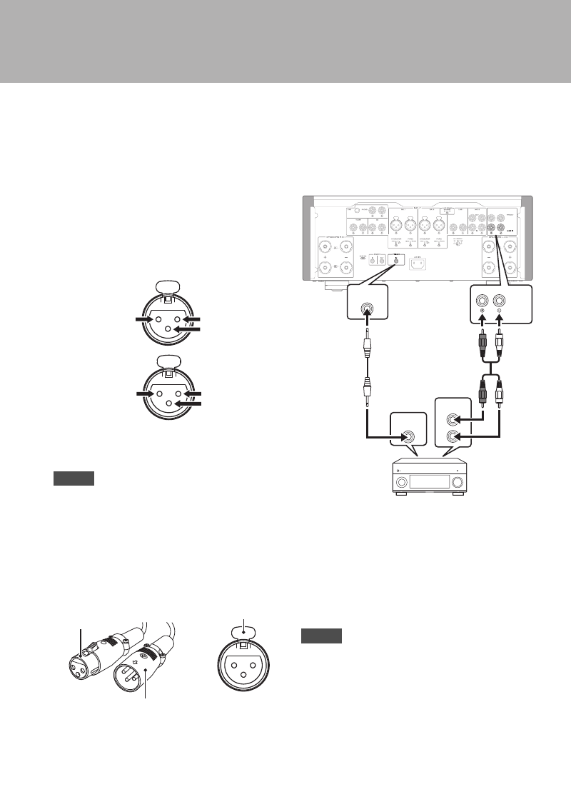
Trigger connection
You can connect a Yamaha AV receiver or other
component that supports the Trigger function. You can
control this unit in sync with a connected component.
When the power to the connected component is turned on,
the power to this unit is also turned on. Simultaneously,
the input source to the unit is set to MAIN DIRECT.
If MAIN DIRECT has been selected as the input source
for this unit, when the power to the connected component
is turned off, this unit will enter standby mode.
When the power switch on this unit is turned Off, the power to
the unit will not be triggered.
Note
1: GND (earth)
2: HOT (+)
3: COLD (−)
NORMAL
(Pin #2: HOT)
1: GND (earth)
2: COLD (−)
3: HOT (+)
INV.
(Pin #3: HOT)
XLR connector
(female)
XLR connector
(male)
Lever
BAL 1/BAL 2
input jack
Note
TRIGGER
OUT
PRE OUT
TRIGGER
IN
MAIN IN
Rear panel of this unit
Yamaha AV receiver or
other component that features
TRIGGER OUT jacks and PRE OUT jacks
Stereo pin cable
Monaural
mini-plug
cable