Connections, Other connection options, Option e: dvd/vcr + tv + rf modulator – Curtis DRC8335 Manuel d'utilisation
Page 8
Other connection options
There are several ways in which you can incorporate your
unit into an Audio-Video system. This depends on the
sockets and other appliances you have. Sound and image
quality depend to a large extent on the types of connections
used.
1. Coaxial audio output (digital sound)
The digital sound of a DVD video disc when played is
permanently available on the coaxial socket of your unit.
Use this socket by connecting it to a decoder or Dolby
Digital amplifier.
2. Component video outputs (Y, Pb, Pr) (YUV)
The Y, Pb, Pr sockets deliver an optimum image quality
8
Connections
,1387
287387
&E
&U
,1387
287387
&E
&U
&+ &+
$8',2 ,1
/
5
9,'(2
,1
72 79
$17 ,1
79
,1387
DVD/VCR
Back of an RF modulator
(example only)
From antenna, cable or satellite
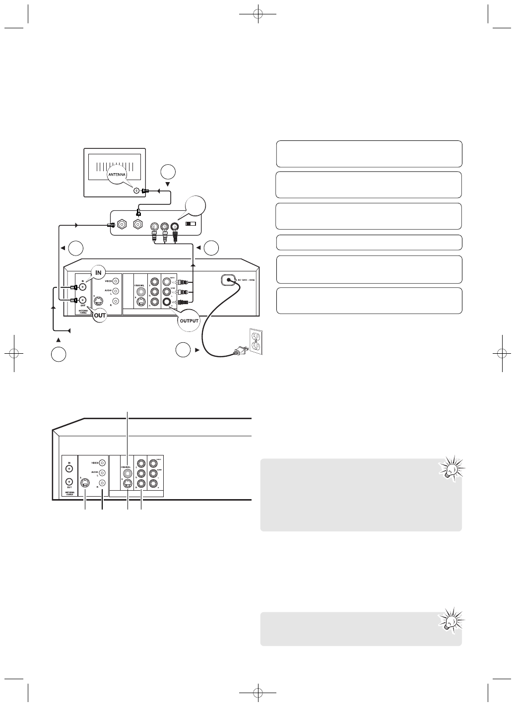
Option E: DVD/VCR + TV + RF Modulator
If your TV does not have AV inputs but only single Antenna input jack, you will need to buy an RF modulator (not provided).
Refer to below for connection details. With this connection, set your TV to channel 3 or 4 in order to view images from the
DVD/VCR recorder.
5
Connect the unit’s AC power cable to a suitable
wall outlet.
6
Your unit is ready for use after the connections.
Please read page 12 to start using the unit.
1
Connect the antenna cable (from antenna, cable
box or satellite) as shown.
2
Connect the RF coaxial cable (from DVD/VCR
recorder to RF modulator) as shown.
3
Connect the provided RF coaxial cable (from RF
modulator to TV) as shown.
4
Connect the included audio cables as shown.
Antenna cable
1
2
3
RF coaxial cable
4
Audio Video
cables
RF coaxial cable
Power cable
5
AC120V 60Hz
due to the separation of the video signal into three
separate components. To obtain the best image quality
possible, use very high quality cables for connections.
Your dealer can provide YUV cables that are sold
together and come in the standard colour codes (red,
green and blue) used for these types of sockets and
cables.
3. S-Video output
The S-Video jack provides better picture quality than a
video jack (sometimes labeled VIDEO and color-coded
yellow on TVs) because S-Video keeps the color part of
the picture separate from the black and white part of the
picture. An S-Video cable is required for connection with
a TV.
If you use the Component sockets Y, Pb, Pr (also
called YUV), you must configure the output video
signal so that these sockets deliver either an
interlaced YUV signal (component interlaced) or a
progressive PS signal (component progressive) by pressing
VIDEO OUT on the remote control. Do not forget to also
connect the audio cables, because Component cables
only transmit images, and not sound.
Remember to connect the left and right audio
cables or coaxial audio cable because S-Video cable
carries only the picture signal, not the sound.
DRC8335_EN(verB) 7/23/07 3:36 PM Page 10