X1 x 2 x 3 – Multi-Contact MA213-01 Manuel d'utilisation
Page 11
Advanced Contact Technology
www.multi-contact.com
11 / 12
Ø3.5
3.
3
5.
2
44
X
1
X
2
X
3
7.
9
7.
9
45
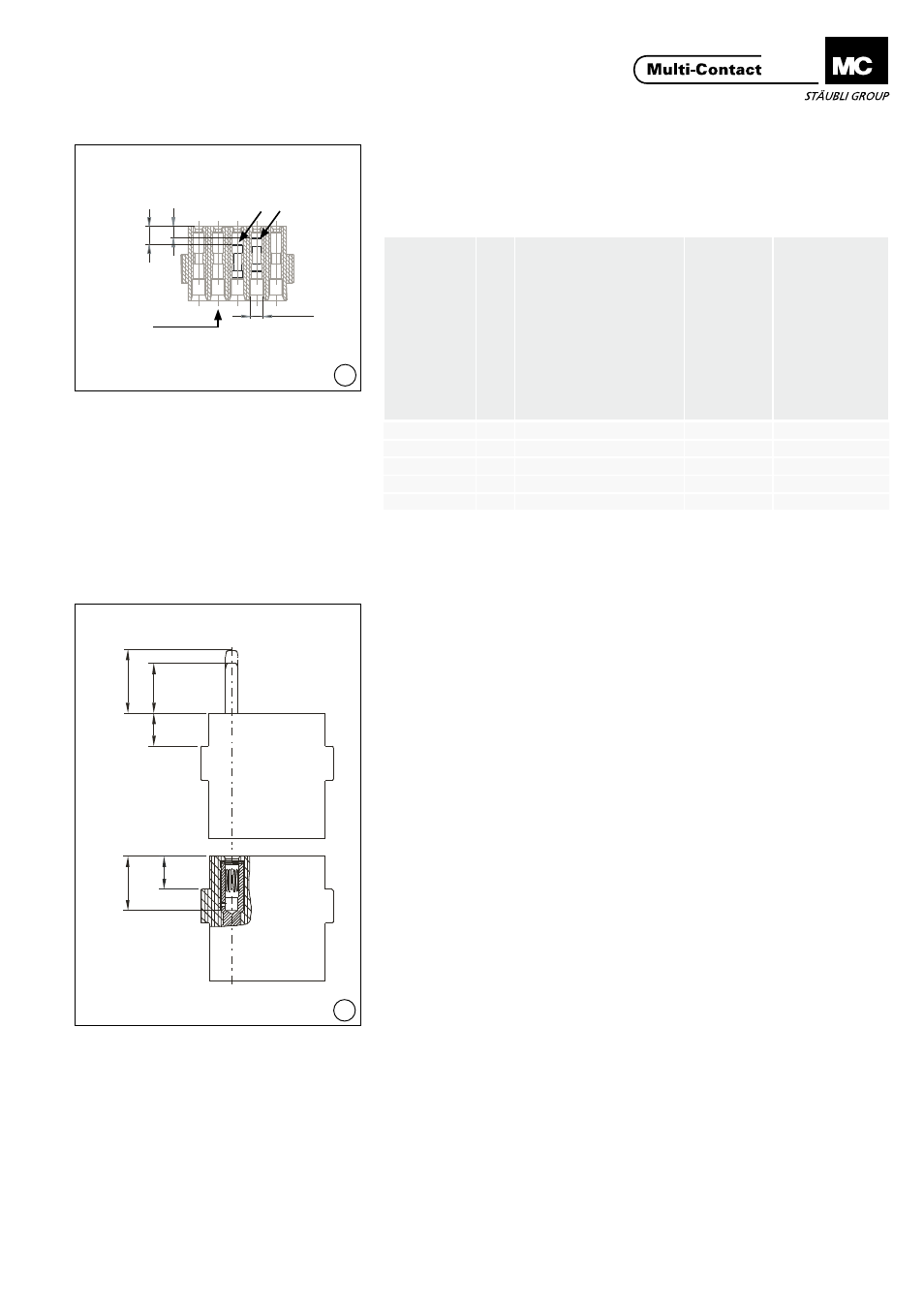
(ill. 44)
Montage des bouchons
d’obturation
(ill. 44)
Assembly of blind plugs
Tab. 3
Tab. 3
Bouchon d’obturation Bl
ind plugs
Ø
Outil
de
montage
/ démontage
Insertion
/ Extraction
tool
No. de Cde. Order No.
Cote de contr
ôle
Contr
ol d
imension
CT-BS1
1
MSA-WZ-1/1,2
18.3002
3,5 mm – 5,1 mm
MVS1
1,5
MSA-WZ-1,5
18.3005
3,3 mm – 5,2 mm
MVS3
3
MSA-WZ-3
18.3012
1 mm – 1,6 mm
MVS5
6
MSA-WZ-5
18.3015
7,5 mm – 8,7 mm
CT-BS8
8
MSA-WZ-8
18.3022
2 mm
Contrôle du montage des
contacts
Checking the contact assembly
(ill. 45)
Vérifier le montage correct des
contacts en contrôlant les cotes X1
(broche), X2 (broche avancée) et X3
(douille)�
(Voir Tab� 4, page 12)�
(ill. 45)
The correct engagement of the
contacts must be checked with the
dimensions X1 (pin), X2 (pin, pre-
mating) and X3 (sockets)�
(See Tab� 4, page 12)�
Pour le CT-06: Le verrouillage correct
des contacts raccordés aux conduc-
teurs dans le support est réalisé en
utilisant l’outil adéquat et en pous-
sant les contacts dans leurs supports
jusqu’en bûtée�
With the CT-0,6 the contacts are cor-
rectly locked in the carriers by press-
ing in the contact parts as far as they
will go with the appropriate tool�
En cas de mauvais montage ou de
réparation, les contacts peuvent
être extraits du support (par la face
de connexion) grâce aux outils de
démontage appropriés (outils de
démontage, voir page 4)�
In the event of pin or socket assign-
ment errors or repairs the contacts
are pushed out of the contact carriers
from the plugging side using the ap-
propriate extraction tools and reinsert-
ed (extraction tools see page 4)�
Bouchon d’obturation
Blind plug
Exemple / Example: MVS1
Sens de montage
Mounting direction