Dc a b e, Sing the device – Thermor Riva 2 Manuel d'utilisation
Page 16
14
5) Programming
The device can be controlled remotely if its pilot wire is connected to a device fitted with a program-
mer, a programming unit or an energy management unit.
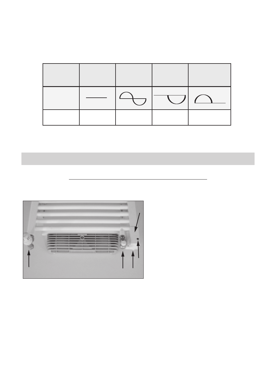
Chart indicating the orders the device can receive over its pilot wire
(to be measured between the pilot wire and the neutral).
U
SING THE DEVICE
CASE OF THE MIXED VERSIONS WITH FAN
1) Description of the lower part of the device.
2) Use on electricity SUMMER SETTING: the central heating circuit is not working.
A switch is on I.The B indicator light is ON, the heating resistor incorporated in the device is sup-
plied.The supply tap C must be closed. The boiler return tap D must remain open.
3) Use on central heating WINTER SETTING: the central heating circuit is working.
A switch is on O.The B indicator light is OFF, the heating resistor incorporated in the device is not
supplied.The supply tap C must be open. The boiler return tap D must remain open.
A
Switch to control the heating resistor
incorporated in the device.
B
Indicator light to check the operating
status of your device.
C
Supply tap to allow inlet of hot water
from the central heating. This can be
thermostatically controlled or not
depending on your choice.
D
Boiler return tap to allow the hot water
to leave the central heating.
Service pressure must not exceed 4 bar.
E
Lower cover.
D
C
A
B
E
Orders received Current absent
Full wave 230V
Negative half
wave -115V
Positive half wave
+115V
Ref/neutral
oscilloscope
Mode achieved
COMFORT
ECO
STANDBY
STOP HEATING
LOAD SHEDDING