3) connecting the device – Thermor Riva 2 Manuel d'utilisation
Page 15
13
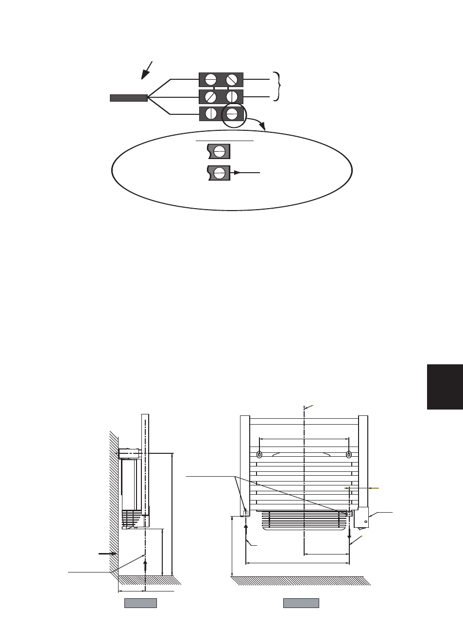
3) Connecting the device
- The device must be supplied with 230V, 50Hz.
- Mains connection must be ensured using the 3-wire cable factory fitte to the heater , through a
connecting box. In damp premises, such as bathrooms and kitchens, install the connecting box at least
25cm from the ground..
- The installation must comply with local national regulation. If in doubt, ask the national Atlantic dis-
tributor.
- Ground connection is forbidden. Do not connect the pilot wire (black) to ground.
- If power cable is damaged or too short, to avoid any danger it must be replaced by a qualified elec-
trician using special tools.
- If a heater pilots or is piloted by a 30mA differential (e.g. bathroom), the pilot wire supply must be
protected on this differential.
4) How to connect the mixed version to the water system ?
For the connection of hot water, the mixed version comprises 2 threaded ports 1/2 gas 15/21 F situa-
ted at the base, as well as a purge with adjustable spray on the top on the right
Follow the flow direction as well as the figures stipulated on the diagram below.
Panel heater cable
Live=brown
Neutral=blue
LIVE
NEUTRAL
Electricity
grid
Two possible cases
Pilot wire=Black
1st case: only one heater
2nd case: multiple heaters
The pilot wire end is insulated
and not further connected
The pilot wire of all heaters in a
control group, up to a maximum
of 20 units with any one them used
as the Master, are connected
by a 1.0mm
2
220-240V insulated cable
WALL
CONNECTION
GROUND
CONNECTION
COVER
Threaded ports
1/2 GAS 15/21 F
WATER INLET
1/2 GAS 15/21 F
mini
122 maxi
115
m
in
i
52
5
m
in
i
20
0
m
in
i
25
9
195
446
80
MIDDLE OF THE DEVICE
WATER OUTLET
1/2 GAS 15/21 F
386
FRONT VIEW
SIDE VIEW
GB