Multi-Contact MA253 Manuel d'utilisation
Page 5
Advanced Contact Technology
www.multi-contact.com
5 / 12
2 mm
12
13
Sertissage des contacts
Crimping-on the contact
parts
(ill. 12)
Introduirelecâbledanslefыtаsertir
et le maintenir pendant le sertissage�
(ill. 12)
Insertcableintothecrimpingsleeve.
During the crimping operation keep
on pushing the cable into the sleeve�
Remarque:
Le toron doit être visible dans
l‘orifice de contrôle avant et après
sertissage. Nous recommandons un
triple sertissage en tournant le câble
60° après le premier et le second
sertissage.
Note:
Wire must be visible in the inspec-
tion hole before and after crimping.
We recommend a triple crimping
operation with a rotation of 60° after
the 1st and the 2nd crimping.
Attention
Aucun brin ne doit dépasser du
fыt а sertir ni avant ni après le
sertissage�
Caution
No wire strands must protrude
from the crimping sleeve either
before or after crimping
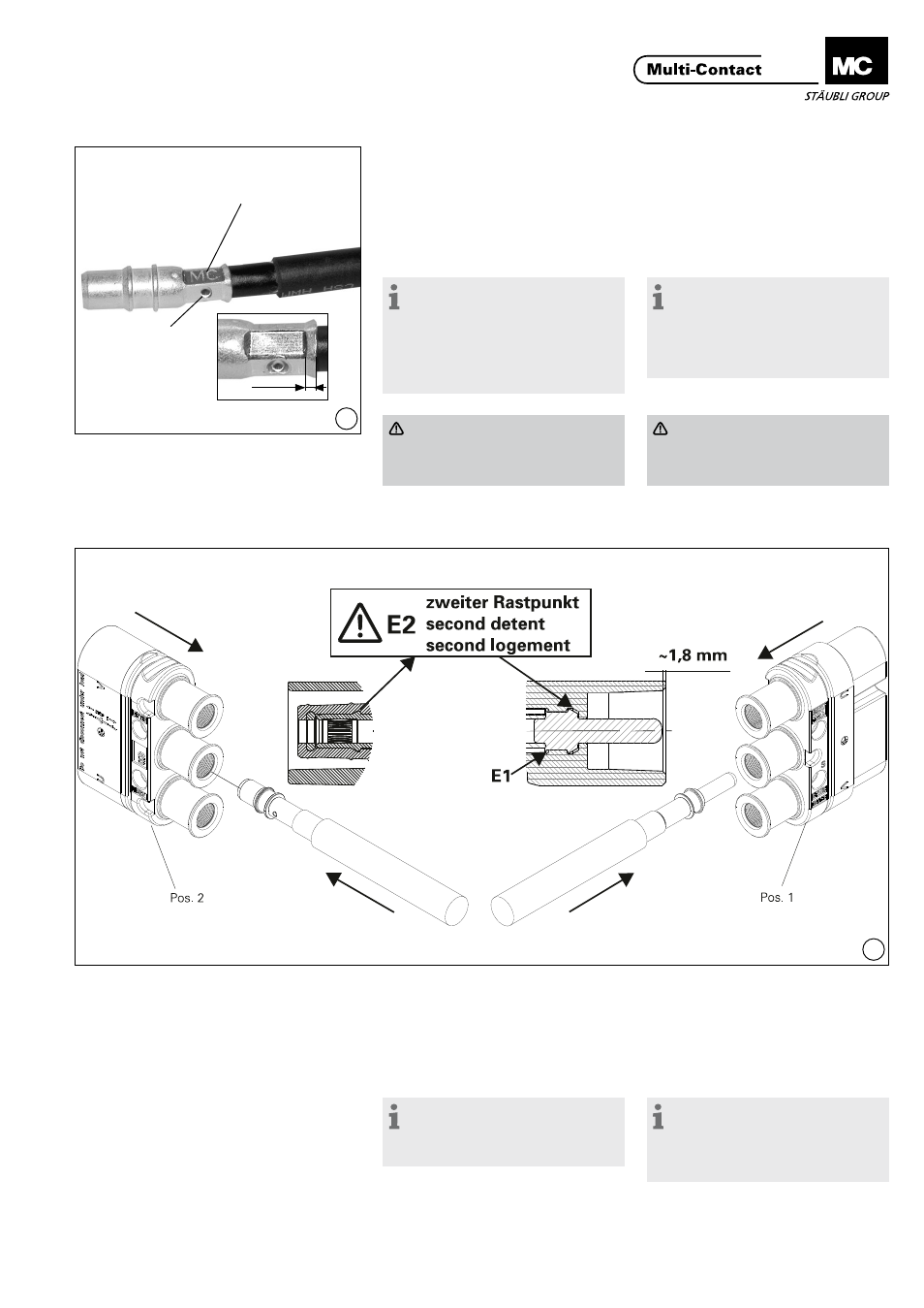
Montage des contacts
Fitting the socket contacts
(ill. 13)
Pousser à la main le câble avec le
contact serti dans le boîtier jusqu‘à
sa mise en place perceptible dans le
second logement (E2) (cf� dimension
de contrôle)�
(ill. 13)
By hand press cable with crimped-on
contact part into the insulation from
the back until it perceptibly engages
into place to the second detent (E2)
(see control dimension)�
Remarque:
Le logement de contact central est
destiné au contact PE et est de ce
fait avancé côté douille.
Note:
The middle contact chamber is
intended for the PE, therefore mating
first and breaking last on the socket
side.
Zone de sertissage
Crimping zone
Orifice de contrôle
Inspection hole