Wiring diagrams – Maytag GLT3057RB Installation Manuel d'utilisation
Page 11
Advertising
11
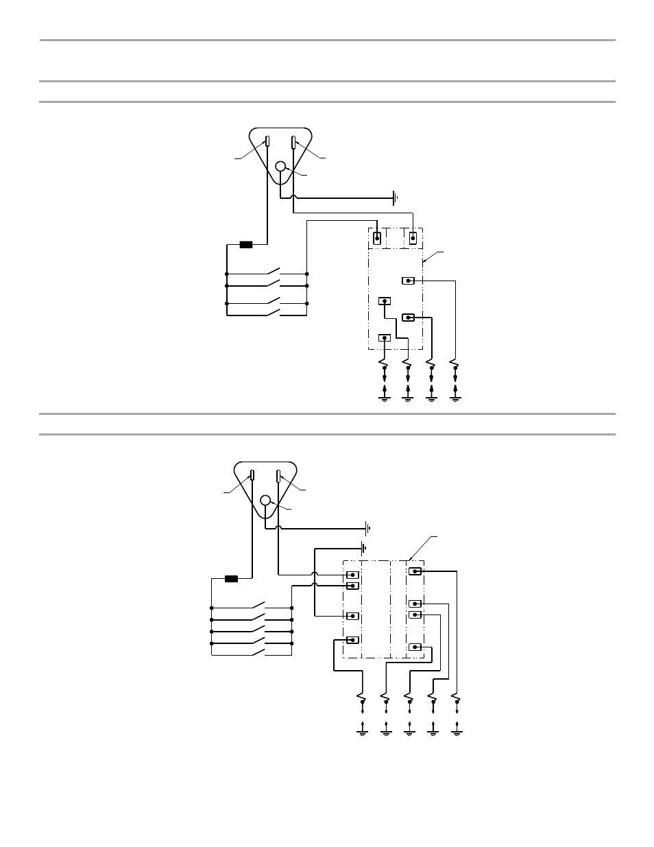
WIRING DIAGRAMS
On 30" (76.2 cm) models
On 36" (91.4 cm) models
Plug
120 VAC 60 Hz
1 Phase
15 or 20 AMP
Neutral
⁵⁄₁₆
" Wide Blade
Ground Round Blade
G or G/Y
GND
W
W
Line
¼" Wide Blade
BK
BK
Connect
.250 Terminals
Valve
Switches
Switches On Valves
Electric Circuit
Closed When Knob Is
Rotated 55˚ to 95˚
Counterclockwise
From OFF
Igniter
Electrodes
Spark
Module
Y or BR
(4) PLCS
Plug
120 VAC 60 Hz
1 Phase
15 or 20 AMP
Neutral
⁵⁄₁₆
" Wide Blade
Ground Round Blade
G or G/Y
G or G/Y
Line
¼" Wide Blade
BK
W
Connect
.250 Terminals
BK
Valve
Switches
Switches On Valves
Electric Circuit
Closed When Knob Is
Rotated 55˚ to 95˚
Counterclockwise
From OFF
Igniter
Electrodes
Y or BR
(4) PLCS
5
4
3
2
GND
L1
N
1
GND
GND
Spark
Module
Advertising