Complete installation – Maytag GLT3057RB Installation Manuel d'utilisation
Page 10
10
Complete Installation
Electronic Ignition System
Initial lighting and gas flame adjustments
Surface burners use electronic igniters in place of standing pilots.
When the cooktop control knob is turned to the “LITE” position,
the system creates a spark to light the burner. This sparking
continues, as long as the control knob is turned to “LITE.”
Check Operation of Surface Burners
Push in and turn the surface burners control knobs to the “LITE”
position.
The surface burner flame should light within 4 seconds. The first
time a surface burner is lighted it may take longer than 4 seconds
to light because of air in the gas line.
Check the flame on “HI” for a blue color. It should be clean and
soft in character. No yellow tip, blowing or lifting of flame should
occur. Occasional orange flashes are normal and reflect different
elements in the air or gas.
After verifying the proper burner operation, turn the control knobs
to “OFF.”
If burners do not light properly:
■
Turn surface burner control knob to the “OFF” position.
■
Check that the power supply cord is plugged in and the
circuit breaker has not tripped or the fuse blown.
■
Check that the gas shutoff valves are set to the “open”
position.
■
Check that burner caps are properly positioned on burner
bases.
Recheck operation of surface burners. If a burner does not light
at this point, contact your dealer or authorized service company
for assistance.
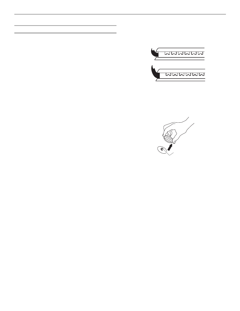
Check Flame Height
Adjust the height of surface burner flames.
The surface burner “low” flame should be a steady blue flame
approximately ¼" (0.64 cm) high.
If the “low” flame needs to be adjusted:
The flame can be adjusted using the adjustment screw in the
center of the valve stem. The valve stem is located directly
underneath the control knob.
1.
Remove the control knob.
2.
Hold the knob stem with a pair of pliers. Use a small flat-
blade screwdriver to turn the screw located in the center of
the control knob stem until the flame is the proper size. Turn
the screw clockwise to decrease the flame height or
counterclockwise to increase the flame height.
3.
Replace the control knob.
4.
Test the flame by turning the control from “LO” to “HI,”
checking the flame at each setting.
A. Low flame
B. High flame
A. Adjustment screw in center of valve stem
A
B
A