Installation du chauffage de pièce - suite, Figure 8, Figure 9 – United States Stove Company 5660 Manuel d'utilisation
Page 16
16
INSTALLATION DU CHAUFFAGE DE PIÈCE - suite
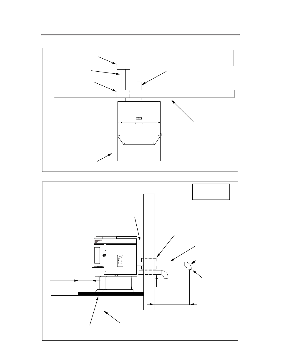
INSTALLATION DE VENTILATION D’ÉVACUATION HORIZONTALE
Figure 8
Listed Horizontal Cap
Exhaust Vent
Wall Thimble Mfg.
by Pellet Vent Mfg.
Combustion Air Intake
6” (152mm)
Clearance to
Combustibles
Floor Protector
6” (152mm) Clearance
Front
Figure 9
6” (152 mm) Clearance
Wall to Back of Unit
Wall Thimble
Exhaust Vent
45 Elbow
or Listed Termination
Rodent Mesh Cap
Combustion Air
Intake
12” (300mm)
Existing Floor
(Combustible)
Non-Combustible
Floor Protection
6” (152 mm)
Admission d’air de combustion
Capuchon horizontal listé
Ventilation
d’évacuation
Manchon mural fabriqué par
un spécialiste de ventilation
Protection de sol sur 6"
(152 mm) à l’avant
Écartement de 6"
(152 mm) par rapport
aux combustibles
Écartement de 6" (152 mm)
entre cloison et arrière d’unité
Manchon mural
Ventilation d’évacuation
Coude à 45° ou
terminaison listée
Capuchon grillagé
anti-rongeurs
Admission d’air
de combustion
Plancher existant
(combustible)
Protection non-combustible
de plancher