Panasonic WV-CU161 Manuel d'utilisation
Wv-cu161, Operating instructions, System controller
Advertising
Before attempting to connect or operate this product,
please read these instructions carefully and save this manual for future use.
Model No.
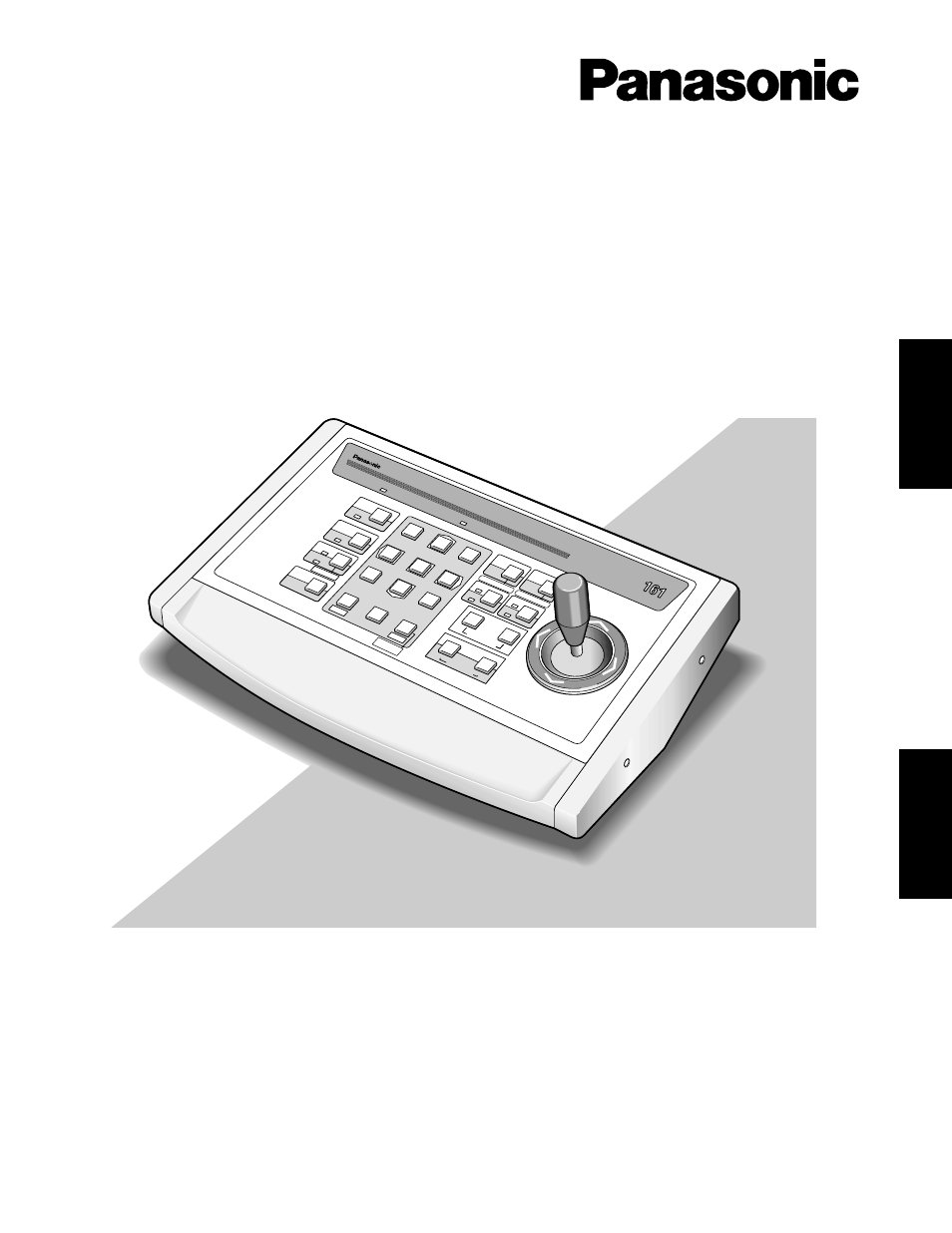
WV-CU161
System Controller
Operating Instructions
Syste
m C
ontr
olle
r W
V-C
U
5
4
1
SHIF
T
ESC
ALA
RM
ALA
RM
OPE
RAT
E
RES
ET
CAM
ERA
SETUP
SET
UP
SLO
W
PROGR
AM
SET
PRE
SET
HOM
E
WID
E
WIP
ER
AUX 1
AUX 2
DEF
PATRO
L
PLAY
CLO
SE
NEA
R
FAR
L
R
UP
DOWN
OPE
N
TEL
E
ZOO
M
IRIS
FOC
US
PATR
OL S
TOP
PATR
OL L
EAR
N
AUT
O
B/W
AUTO
FOC
US
IRIS RESET
PRO
GR
AM
PRE
SET
CAMERA
FUNCTION
SUSPEND
2
0
6
3
9
8
7
ENGLISH
FRANÇAIS
Advertising
Table des MATIÈRES
Document Outline
- TABLE OF CONTENTS
- PREFACE
- FEATURES
- PRECAUTIONS
- MAJOR OPERATING CONTROLS AND THEIR FUNCTIONS
- SETUP
- CONNECTIONS
- SYSTEM CONNECTIONS
- SETUP MENU
- OPERATING PROCEDURES
- INSTALLATION
- ALL RESET
- SPECIFICATIONS
- TABLE DES MATIERES
- PREFACE
- CARACTERISTIQUES DOMINANTES
- MESURES DE PRECAUTION
- PRINCIPAUX ORGANES DE COMMANDE ET LEURS FONCTIONS
- CONFIGURATION
- BRANCHEMENTS
- BRANCHEMENT DE SYSTEME
- BRANCHEMENT DE BASE
- RACCORDEMENT A UN COMMUTATEUR CYCLIQUE VIDEO
- RACCORDEMENT DE COMMUNICATION DE SITE RS-485 PAR CODEC POUR UNE DISTANCE D'ELOIGNEMENT A UNE CAMERA
- VIDEO DE SURVEILLANCE EGALE OU SUPERIEURE A 1 200 M (4 000 PD.)
- RACCORDEMENT A UN MAGNETOSCOPE D'ENREGISTREMENT LONGUE DUREE
- REGLAGE DE COMPENSATION DE PERTES DANS LES CABLES
- BORNE RS-485
- MENU DE CONFIGURATION
- PROCEDURES D'UTILISATION
- INSTALLATION
- REMISE A ZERO GENERALE
- CARACTERISTIQUES TECHNIQUES