Analog Way Octo Fade - OFD802 Manuel d'utilisation
Page 6
Chapter 1 : INTRODUCTION (continued)
OCTO range
PAGE 6
1-3. DEVICES & OPTIONS REFERENCES
REFERENCE
DESIGNATION
OCP802 OCTO-PLUS
™
.
OLG802 OCTO-LOGO
™
.
OFD802 OCTO-FADE
™
.
OFX802 OCTO-FX
™
.
OPT-VOV802
Voice Over control for microphone (optional).
OPT-LAN
LAN communication port (optional)
RK802-F
Remote KEYPAD for controlling an OCTO device (optional).
10077
CABLE (HD15 M / HD15 M) L = 1.8 m
10023
CABLE (HD15 M / 5BNC M) L = 1.8 m
10102
CABLE (4-pin mini DIN M / 2BNC M) L = 1.8 m
10009
CABLE (4-pin mini DIN M / 4-pin mini DIN M) L = 1.2 m (optional).
10123
CABLE (HD15 M / 5BNC F) L = 0.5 m (optional).
10124
CABLE (4-pin mini DIN F / HD15 M) L = 0.2 m (optional).
1-4. INSTALLATION
IMPORTANT:
Please read all the safety instructions (pages 2 to 4) before starting.
• Table Top Mounting: The OCTO can be used directly on a table: the unit is equipped with 4 plastic feet.
• Rack Mounting:
The OCTO is compatible with a 19" enclosure. To install the OCTO into a 19” rack: Attach the
OCTO to the rack by using 4 screws in the front panel holes (screws are not included).
IMPORTANT:
• The openings in the rear and side panels are for cooling. Do not cover these openings.
• Be sure that no weight is added to the OCTO in excess of 2 kg (4.4 lbs.).
• The maximum ambient operating temperature must not exceed 40°C (104°F).
• The rack and all mounted equipment in it must be reliably grounded to national and
local electrical codes.
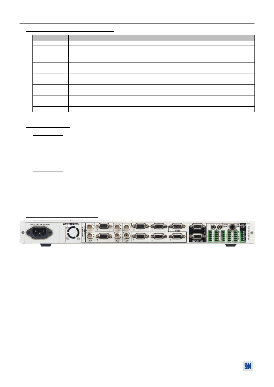
1-5. REAR PANEL DESCRIPTION
POWER:
Standard IEC connector (100-250VAC, 1A, 50-60Hz automatic).
LAN:
LAN communication port on a RJ45 connector.
COMPUTER & VIDEO INPUTS:
7 Universal (computer and video) inputs.
INPUTS #1, 2 & 3:
Computer, YUV and HDTV signals on the HD15 female input connector.
S.VIDEO (Y/C) signal on 2 BNC input connectors (Y & C).
Composite Video on one BNC input connector (C.V).
INPUTS # 4, 5, 6, & 7:
All signals on a HD15 female connector.
DISPLAY OUT:
2 buffered DATA outputs (RGBHV or RGB/S) on HD15 female connectors.
AUDIO IN:
1 to 5:
Audio stereo input balanced/unbalanced on a 5-pin MCO male connector.
6 & 7:
Audio stereo input unbalanced on a jack 3.5 mm female connector.
MIC (bal):
Microphone balanced input (jack 6.35 mm female connector).
AUDIO OUT:
Audio stereo output balanced/unbalanced on a 5-pin MCO male connector.
RS-232:
RS-232 communication port on a DB9 female connector.