Multi-Contact MA030 Manuel d'utilisation
Page 6
Advanced Contact Technology
6 / 8
www.multi-contact.com
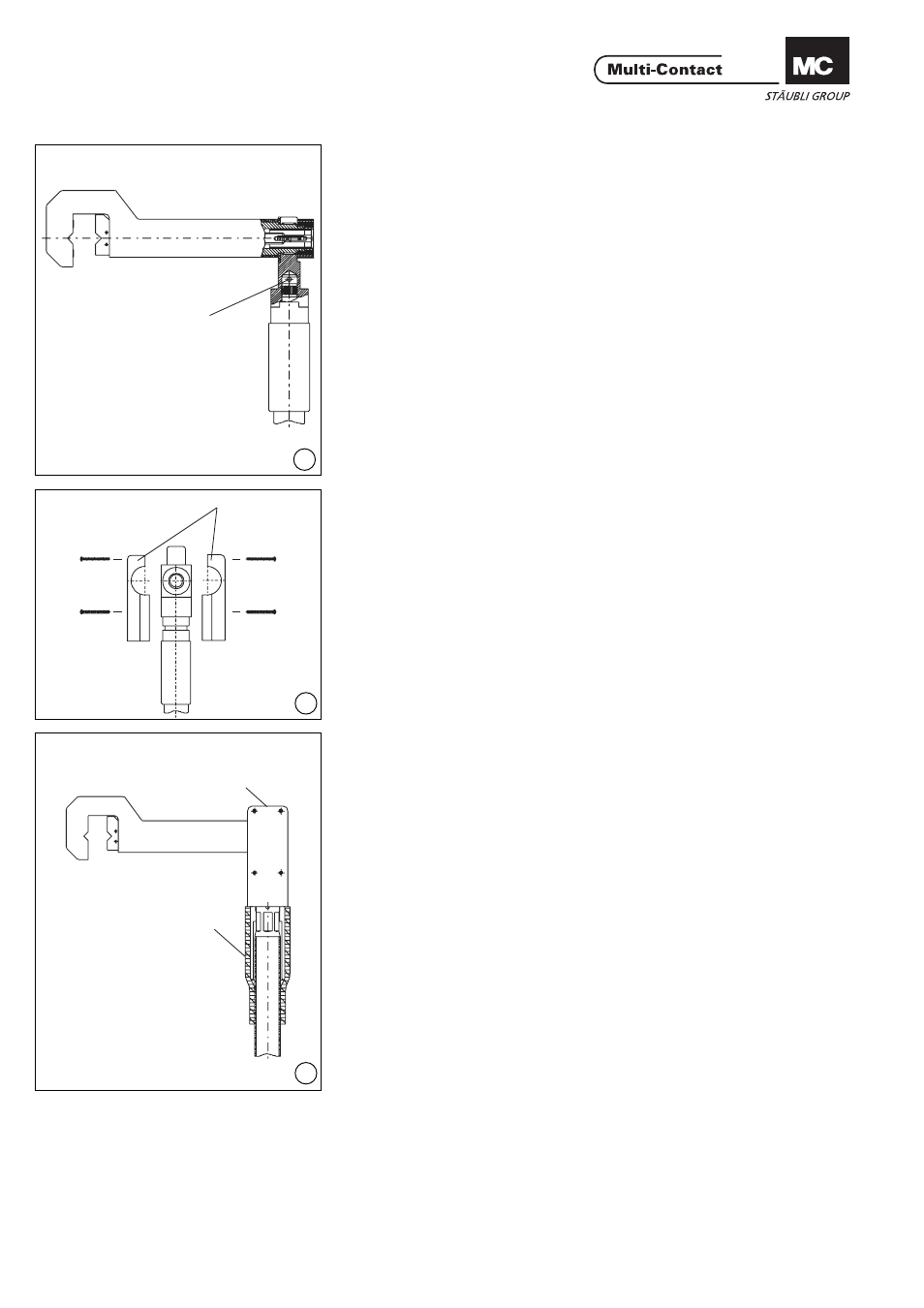
B
12
5
13
5
4
14
(ill. 12)
Embrocher la fi che jusqu‘en butée
dans la douille de réception. Sur une
perceuse d‘établi, orienter le perçage
transversal de la douille de réception
(B) perpendiculairement au foret et
percer avec un foret hélicoïdal de
Ø4mm.
Veiller à ce qu‘aucun copeau de per-
çage ne se trouve dans la douille de
réception.
Ensuite, introduire la goupille fen-
due Ø 4x30 dans le perçage avec un
marteau.
(ill. 12)
Push the plug into the locating socket
as far as it will go. Line up the lateral
hole in the locating socket (B) with a
bench drill vertically to the drill, and
bore a hole with a Ø 4mm spiral drill.
Ensure that no drill shavings get into
the locating socket. Then use a ham-
mer to drive the Ø 4x30 heavy type
dowel pin into the hole.
(ill. 13)
Assembler les deux demi-coques
d‘isolation (5) et les visser ensemble
avec les vis PT (pour thermoplast
KA3.5x35).
(ill. 13)
Fit both insulation shells (5) and screw
together with PT-Screws (for thermo-
plast, KA3.5 x 35).
La confection du câble se termine
ici, si le diamètre extérieur du câble
correspond à la dimension de contrôle
(Tab. 1, page 4/8).
The cable assembly is now fi nished
if the measured diameter is equal to
dimension
Prüfmass
(according to
Tab. 1, page 4/8).
(ill. 14)
Après le montage des demi-coques
d’isolation (5) glisser la gaine ther-
morétractable (4) jusqu’en butée et
rétreindre la gaine thermorétractable
uniformément au générateur d’air
chaud.
(ill. 14)
After assembly of the insulation shells
(5) push the shrink sleeve (4)on up to
the shells and shrink evenly with a hot
air blower.