Multi-Contact MA030 Manuel d'utilisation
Page 5
Advanced Contact Technology
www.multi-contact.com
5 / 8
X
9
10
min. 16mm
3
4
11
3
Le
ite
r Ø
Y
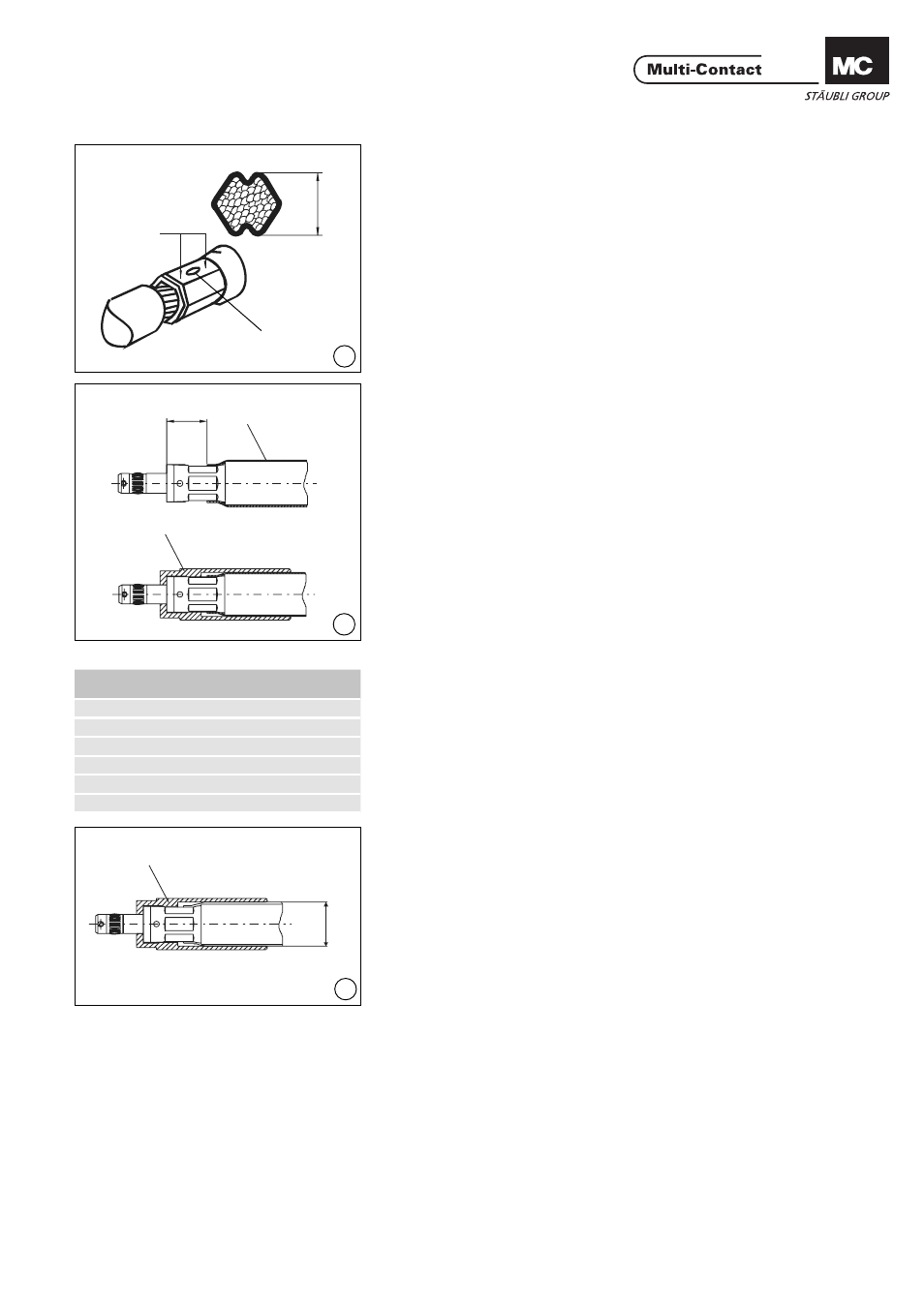
(ill. 9)
Vérifi cation des résultats de ser-
tissage
La déformation du fыt а sertir permet
de vérifi er si le sertissage a été correc-
tement effectué par l‘outil.
Pour ce faire, vérifi er au pied à
coulisse la dimension X des surfaces
hexagonales créées par le poinçon.
La dimension X mesurée doit coïn-
cider avec la dimension de contrôle
fi gurant dans le tableau (Tab.1, page
4/8).
(ill. 9)
Evaluation of the crimping results.
It can be determined from the defor-
mation of the crimping sleeve whether
the crimping has been crimped cor-
rectly or not.
This is done by checking with a caliper
the dimension X of the hexagon
surfaces where the crimping die has
made an indentation.
The measured dimension X should
agree with the test dimension stated
in the table (Tab. 1, page 4/8).
(ill. 10)
Mesurer le diamètre extérieur Y du
câble.
Si le résultat correspond à la dimen-
sion Ø >... (Tab. 3), glisser d’abord la
gaine thermorétractable sur le câble et
poursuivre par ill. 11 jusqu’à ill. 14.
Si la dimension est égale а Ш <...,
monter la gaine thermorétractable
(4) directement sur le fыt а sertir et le
câble. Enfi ler la gaine thermorétrac-
table sur le câble. Respecter la dimen-
sion 16mm et rétreindre la gaine
thermorétractable uniformément au
générateur d‘air chaud. Glisser ensuite
l‘isolation (3) sur le fыt а sertir.
Poursuivre par (ill. 12).
(ill. 10)
Measure outside Ø Y of cable.
If the measured diameter is equal to
dimension Ø >... (according to Tab.3),
then push the shrink sleeve fi rst on
the cable and continue as from ill. 11
up to ill. 14.
If the measured diameter is equal
to dimension Ø <..., then the shrink
sleeve (4) is shrunk directly onto the
crimp and the cable. Push shrink
sleeve onto cable. Observe dimen-
sion of 16mm and evenly shrink on
the sleeve with a hot-air blower. Then
push insulation over crimping sleeve.
Continue as from (ill. 12).
(ill. 11)
Glisser l‘isolation (3) sur le fыt а sertir.
(ill. 11)
Push insulation (3) over crimping
sleeve.
Points de mesure
Measurement
points
Empreinte de sertissage
Crimp mark
Tab. 3
Section du câble
Conductor cross section
Ø câble Y
Conductor Ø Y
50mm
2
<17
≥17
70mm
2
<20
≥20
95mm
2
<23
≥23
120mm
2
<25
≥25
150mm
2
<28
≥28
185mm
2
<31
≥31
Câble Ø Y
Conductor Ø Y