Annexes, 1 câblage des connecteurs principaux – SONOSAX SX-ES64 Manuel d'utilisation
Page 20
Mode d’emploi SONOSAX SX-ES64
Page 20 de 27
7.
ANNEXES
7.1.1
Câblage des connecteurs principaux
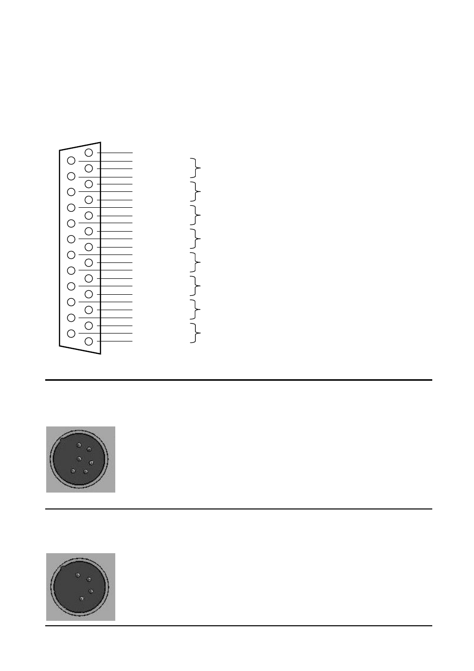
LINE OUT
25 pin Sub-D female
Mating cable connector:
25 pin Sub-D male
13 => n.c.
25 => ground
12 => Low -
Direct Out Channel 1
24 => High +
11 => ground
23 => Low -
Direct Out Channel 2
10 => High +
22 => ground
9 => Low -
Direct Out Channel 3
21 => High +
8
=>
ground
20 => Low -
Direct Out Channel 4
7 => High +
19 => ground
6 => Low -
Direct Out Channel 5
18 => High +
5
=>
ground
17 => Low -
Direct Out Channel 6
4 => High +
16 => ground
3 => Low -
Main Out 1 (internally wired in parallel with XLR OUT 1)
15 => High +
2
=>
ground
14=>
Low -
Main Out 2 (internally wired in parallel with XLR OUT 2)
1 => High +
MON2/PL
XLR-6M
Compatible with SONOSAX BOOM BOX
Mating cable connector: XLR-6F
Pin 1 = Monitor 2 Out LEFT
Pin 2 = Monitor 2 Out RIGHT
Pin 3 = Monitor 2 Gnd
Pin 4 = PL microphone Hi +
Pin 5 = PL microphone Lo -
Pin 6 = PL microphone Gnd & CALL
Bridge Pin 6 ( Gnd/CALL ) and pin 3 (Gnd ) via a switch to activate the PL1 CALL function
EXT DC IN 6 to 18 Volts
XLR-4M
Mating cable connector: XLR-4F
Pin 1 = GND
Pin 2 = n.c
Pin 3 = n.c
Pin 4 = Positive DC Voltage 6 to 18 Volts