Alarm port connection, Alarm – 
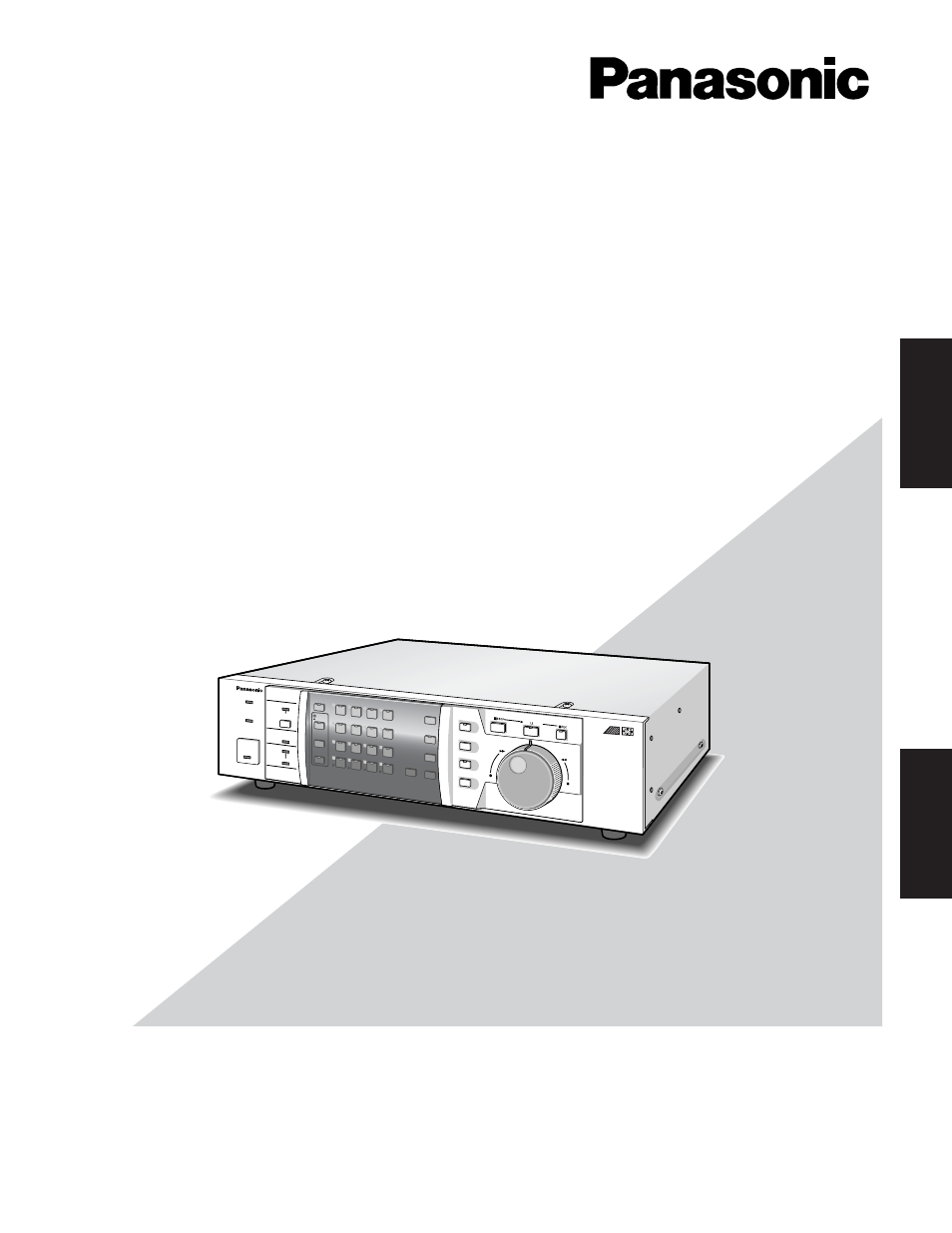
Panasonic WJ-HD500A Manuel d'utilisation

Page 18

Advertising
background image

18

Alarm Port Connection

The ALARM port can be used for connecting the alarm sen-
sor and alarm control switches. It is also used to synchro-
nize the sequence as shown below.

• Connect the sensor switches to the ALARM port on the

rear of the Disk Recorder, as shown in the example
below.

Designation

Pin

No.

1

2

3

4

5

6

7

8

9

10

11

12

13

Alarm Input 1

Alarm Input 2

Alarm Input 3

Alarm Input 4

Sequence Timing Input

Alarm Reset Output

Ground

Alarm Recover Input

Alarm Output

Alarm Input 10

Alarm Input 11

Alarm Input 12

Alarm Input 13

Pin

No.

14

15

16

17

18

19

20

21

22

23

24

25

Designation

Ground

Alarm Input 5

Alarm Input 6

Alarm Input 7

Alarm Input 8

Alarm Input 9

Ground

+5 V Output (0.2 A)

Recording Timer Select
Input

Alarm Input 14

Alarm Input 15

Alarm Input 16

ALARM

1

13

14

25

• The sequence timing can be assigned to one of the

recorders when the multiple Disk Recorders are
equipped in the system.
Connect the CONTROL port and ALARM port as shown
below.
Refer to the SEQ TIMING in the SEQUENCE SETUP
menu for further setting.

If the sequence timing is controlled from the outboard
device, the input signal is required as shown in the fig-
ure. For example, the WJ-HD500A output is also in the
figure.

CONTROL

5

7

Ground

Sequence Timing Input

ALARM

WJ-HD500A (1st)

WJ-HD500A (2nd)

15

4

Sequence Timing Output

Ground

input

100 ms 100 ms

WJ-HD500A
output

500 ms

100 ms

Advertising