Warning, Complete installation – Maytag W5CG3024XS Installation Manuel d'utilisation
Page 9
9
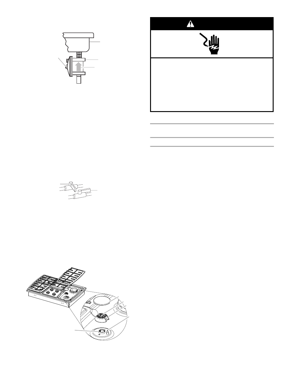
4. Install the pressure regulator with the arrow pointing up
toward the bottom of the cooktop base and in a position
where you can reach the regulator access cap.
IMPORTANT: All connections must be wrench-tightened. Do not
make connections to the gas regulator too tight. Making the
connections too tight may crack the regulator and cause a gas
leak. Do not allow the regulator to turn on the pipe when
tightening fittings.
Use only pipe-joint compound made for use with Natural and LP
gas.
Do not use TEFLON
®
tape. You will need to determine the fittings
required depending on your installation.
Complete Connection
1. Open the manual shutoff valve in the gas supply line. The
valve is open when the handle is parallel to the gas pipe.
2. Test all connections by brushing on an approved
noncorrosive leak-detection solution. Bubbles will show a
leak. Correct any leak found.
3. Remove surface burner caps, burner base and grates from
parts package. Align notches in burner caps with pins in
burner base.
Align orifice holder in burner base with igniter electrode.
Burner caps should be level when properly positioned. If
burner caps are not properly positioned, surface burners will
not light. Place burner grates over burners and caps.
4. Plug into a grounded 3 prong outlet.
Complete Installation
Electronic Ignition System
Initial lighting and gas flame adjustments
Surface burners use electronic igniters in place of standing pilots.
When the cooktop control knob is turned to the “IGNITE”
position, the system creates a spark to light the burner. This
sparking continues, as long as the control knob is turned to
“IGNITE.”
Check Operation of Surface Burners
Push in and turn the surface burners control knobs to light.
The surface burner flame should light within 4 seconds. The first
time a surface burner is lighted it may take longer that 4 seconds
to light because of air in the gas line.
Check the flame on “HIGH” for a blue color. It should be clean
and soft in character. No yellow tip, blowing or lifting of flame
should occur. Occasional orange flashes are normal and reflect
different elements in the air or gas.
After verifying the proper burner operation, turn the control knobs
to “OFF.”
If burners do not light properly:
■
Turn surface burner control knob to the “OFF” position.
■
Check that the power supply cord is plugged in and the
circuit breaker has not tripped or the fuse blown.
■
Check that the gas shutoff valves are set to the “open”
position.
■
Check that burner caps are properly positioned on burner
bases.
Recheck operation of surface burners. If a burner does not light
at this point, contact your dealer or authorized service company
for assistance.
A. Access cap
B. Rear of cooktop
C. Gas pressure regulator
D. Up arrow. Regulator must be installed with
arrow pointing up to cooktop bottom.
A. Closed valve
B. Open valve
A. Orifice holder
B. Burner cap
C. Gas tube opening
D. Burner base
E. Igniter electrode
A
B
C
D
A
B
B
C
D
E
A
Electrical Shock Hazard
Plug into a grounded 3 prong outlet.
Do not remove ground prong.
Do not use an adapter.
Do not use an extension cord.
Failure to follow these instructions can result in death,
fire, or electrical shock.
WARNING