Thermor Allure Manuel d'utilisation
Page 16
15
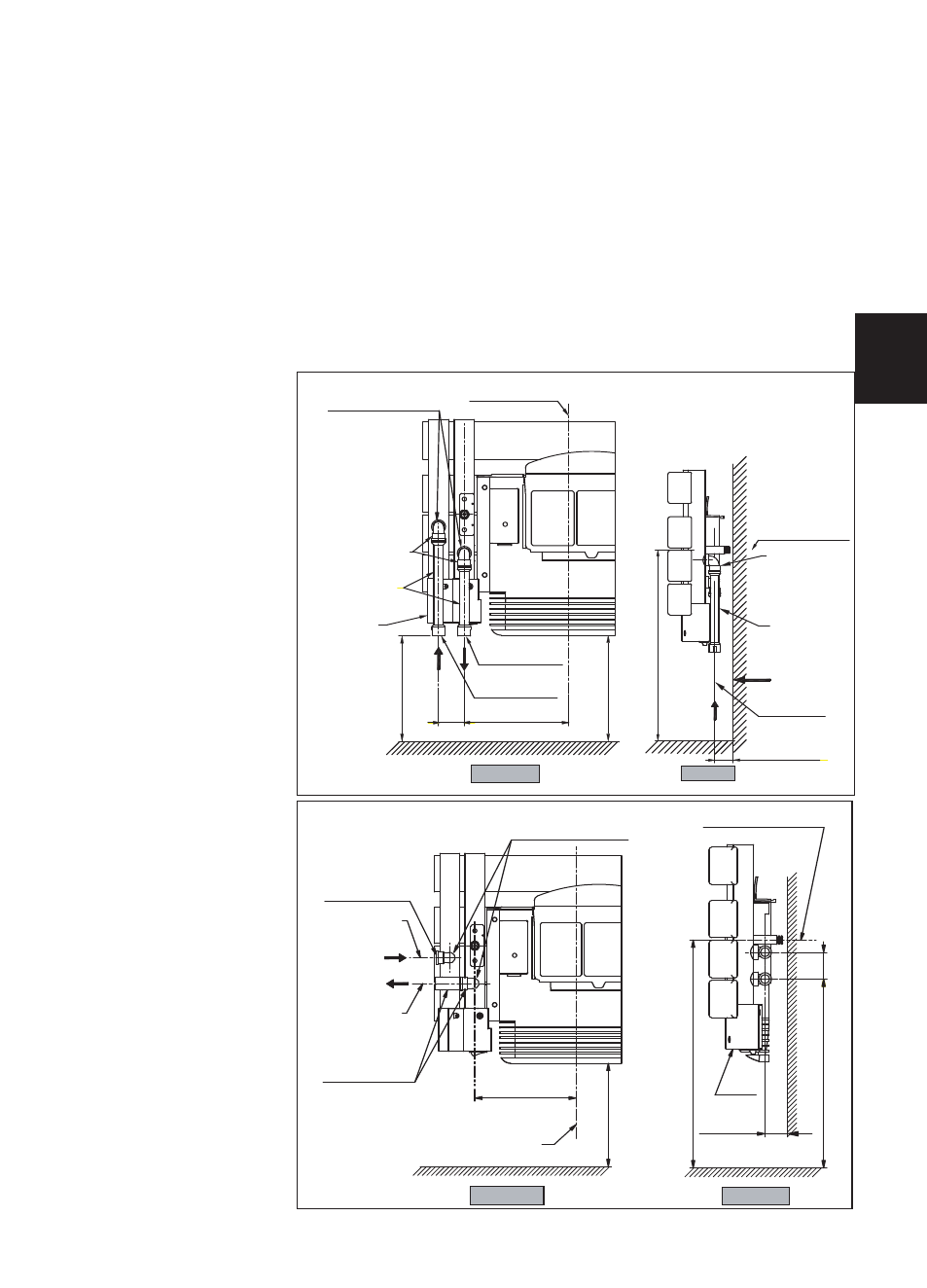
4) How to connect the mixed version to the water system ?
For the connection of hot water, the mixed version comprises 2 threaded ports 1/2 gas 15/21 F situa-
ted at the base, as well as a purge with adjustable spray on the top on the right
There are two types of connections:
Type 1: Connection for water at the base.
Type 2: Connection for water on the right hand side.
- For type 1, place two 90° standard elbows on the T connections at the back of the device (elbows
not supplied). Position the two extensions supplied on the 90° elbows.
- For type 2, place two 90° standard elbows on the T connections at the back of the device (elbows
not supplied). Position a 50mm extension (standard on the market) on the bottom elbow (extension
not supplied).
Follow the flow direction as well as the figures stipulated on the diagram below.
COVER
Threaded ports
1/2 GAS 15/21 F
WATER INLET
1/2 GAS 15/21 F
90° ELBOW +
50mm EXTENSIONS
(not supplied)
90° ELBOW
(not supplied)
MIDDLE OF THE DEVICE
WATER OUTLET
1/2 GAS 15/21 F
50
39 MINIMUM
47 MAXIMUM
M
IN
IM
U
M
35
4,
5
42
8
M
IN
IM
U
M
LOWER WALL
FIXTURE LINE
197
M
IN
IM
U
M
20
0
REAR VIEW
SIDE VIEW
39 MINIMUM
47 MAXIMUM
M
IN
IM
U
M
19
8,
5
M
IN
IM
U
M
20
0
50
197
90° ELBOW
(not supplied)
EXTENSIONS
(supplied)
WALL
CONNECTION
GROUND
CONNECTION
42
8
M
IN
IM
U
M
COVER
90° ELBOW
(not supplied)
EXTENSIONS
(supplied)
WATER INLET
1/2 GAS 15/21 F
WATER OUTLET
1/2 GAS 15/21 F
Threaded ports
1/2 GAS 15/21 F
MIDDLE OF THE DEVICE
REAR VIEW
SIDE VIEW
LOWER WALL
FIXTURE LINE
TYPE 1:
CONNECTION AT
THE BASE
TYPE 2 :
CONNECTION ON
THE RIGHT HAND
SIDE
GB