Amplifier installation installation warnings, Connection – Fusion EN-1502 Manuel d'utilisation
Page 3
3
AMPLIFIER INSTALLATION
INSTALLATION WARNINGS
1. Ensure the +12V lead is disconnected from the battery before you connect any new
equipment.
2. Ensure that the amplifier mounting location and holes will not interfere with the gas tank,
brake lines or electrical wiring.
3. Ensure the amplifier is securely fastened to the vehicle to prevent the amplifier moving and
causing damage in the event of an accident.
4. Ensure all wiring is protected from sharp objects and from pinching or crushing which
could result in damage to the audio system.
5. Ensure the mounting location has sufficient air flow around the amplifier. If the amplifier is
mounted in an enclosed space a 3” fan with ducting should be used to assist with cooling.
6. Do not mount any amplifier on a subwoofer enclosure as extended exposure to vibration
may cause damage to the amplifier.
7. Ensure you use the minimum recommended gauge wire/cable or larger for all amplifier
connections.
8. Appropriate mounting is very important for prolonged life expectancy of any amplifier.
Select a location that provides protection from moisture. Keep in mind that an amplifier
should never be mounted upside down. Upside down mounting will compromise heat
dissipation through the heat sink and could engage the thermal protection circuit.
CONNECTION
Ensure the audio system is turned off before making any connections to the amplifier,
speakers or source unit. Failure to do so could result in permanent damage to the audio
system.
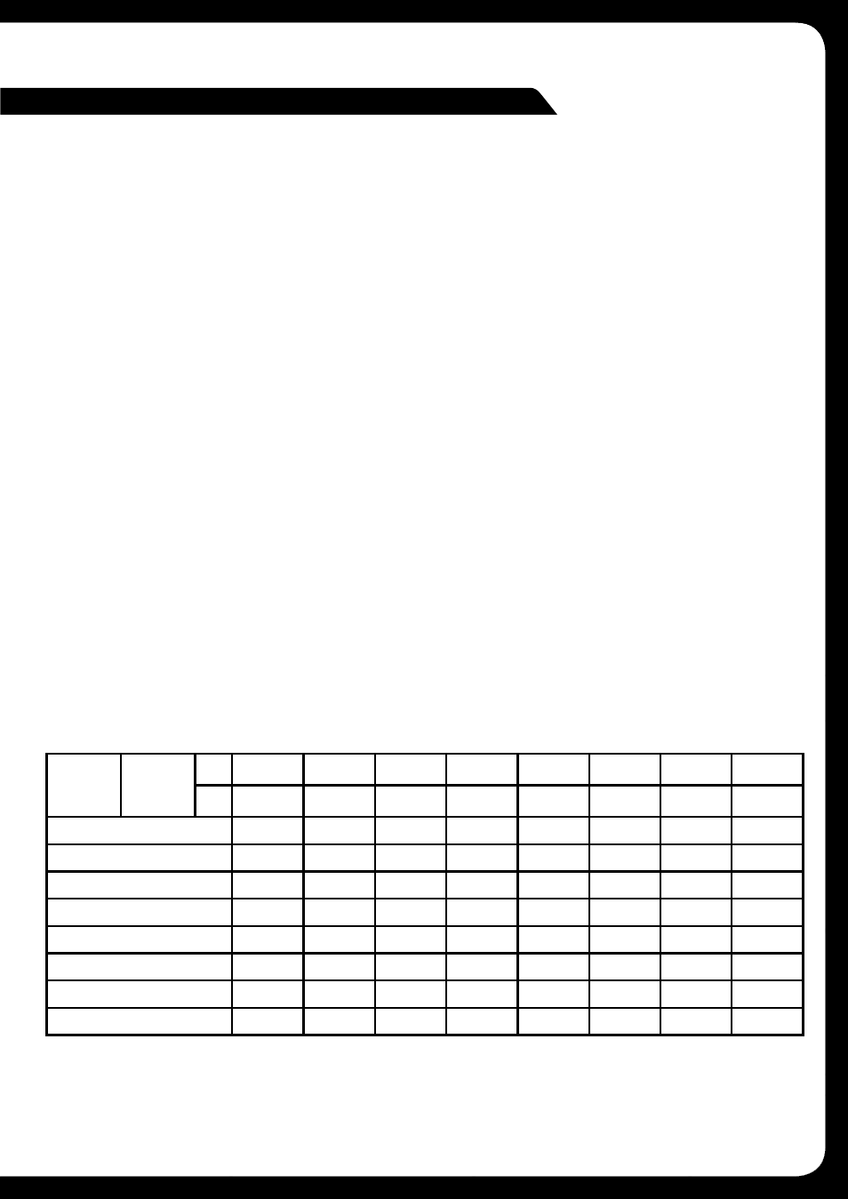
Ensure the correct gauge cable is used for all connections; consult the cable calculator
diagram below for the correct gauge cable for your installation.
TOTAL
AMPS
CABLE
LENGTH
>
M
0 - 1
1 - 2
2 - 3
3 - 4
4 - 5
5 - 6
6 - 7
7 - 9
FT
0- 4
4 - 7
7 - 10
10 - 13
13 - 16
16 - 19
19 - 22
22 - 28
0 - 20
14
12
12
10
10
8
8
8
20 - 35
12
10
8
8
6
6
6
4
35 - 50
10
8
8
6
4
4
4
4
50 - 65
8
8
6
4
4
4
4
2
65 - 85
6
6
4
4
2
2
2
0
85 - 105
6
6
4
2
2
2
2
0
105 - 125
4
4
4
2
0
0
0
0
125 - 150
2
2
2
0
0
0
0
0
The above chart shows cable gauges to be used, if no less than a 0.5 volt drop is acceptable.
If aluminium wire is used, the gauges should be of an even larger size to compensate. Cable
gauge size calculation takes into account terminal connection resistance.