Caple CR9202 Manuel d'utilisation
Page 9
GAS ADJUSTMENT
Z
APPLIANCE MAINTENANCE
E 14
25 W - 230 V~
T300°C
A
REPLACEMENT OF THE CABLE
In case the cable is damaged, replace it in accordance with the
following instructions:
- open the box of the supply board as described on the picture
below;
- unscrew screw “A” fixing the cable;
- replace the cable with one of the same lenght and in accordance
with the features described on the table; switch the appliance
off, and close the gas tap
- the ‘green-yellow” earth wire must be connected to the terminal
“ “ and it must be about 10 mm longer thean the live wires;
- the “blue” neutral wire must be connected to the terminal marked
with letter “N”;
- the live wire must be connected to the terminal marked with letter
“L”.
Conversion to LPG
Always isolate the cooker from the electricity supply, turn off the
gas supply temporarily and proceed as follows.
- change the injectors,
- adjust the minimum flow of the burners.
REPLACEMENT OF WORK-TOP INJECTORS
In order to change the work-top injectors, it is necessary to act as
follows: remove the grids, remove burners and flame-spreaders
(see fig.A), change the injector (see fig.B) and replace it with
another one suitable for the new type of gas (see table D). Re-
assemble everything in the opposite direction, paying attention to
place the flame-spreader in the right way on the burner.
TAB. D
GENERAL INJECTORS TABLE
Kind of gas
mbar Nozzle
Burners
Power Watt
Consum.
mm/100
Posizione-type
max.
min.
max.
115
-Rapide
3000
750
286 l/h
NATURAL
20
97
-Semi rapide
1750
480
167 l/h
72
-Auxiliary
1000
330
95 l/h
128 -Triple crown
3300 1300 315 l/h
120
- Fish
2900
1500
277 l/h
G.P.L.
30
85
-Rapide
3000
750
219 g/h
BUTANE
28
65
-Semi rapide
1750
480
128 g/h
PROPANE
37
50
-Auxiliary
1000
330
73 g/h
93
-Triple crown
3300
1300
241 g/h
85
- Fish
2900
1500
211 g/h
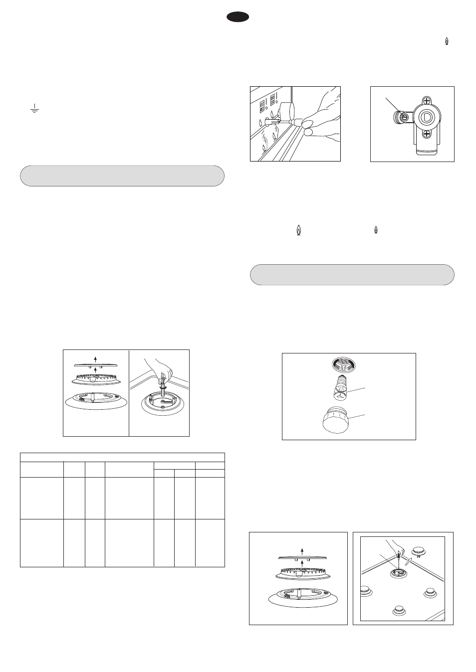
Fig. 14
Fig. 15
MINIMUM FLOW ADJUSTMENT FOR WORK-TOP TAPS
In order to adjust the minimum, act as follows: switch the burner
on, and turn the knob towards the minimum flow position .
Remove the knob from the tap, introduce a little screwdriver in
the tap rod (fig. 14).
Attention: in taps with security valve, the minimum adjusting screw
“Z” is placed outside the rod tap (fig. 15).
Unscrew the adjusting screw in order to increase the flow or screw
it to decrease the flow.
The right adjustment is obtained when the flame has a length of
about 3 or 4 mm.
For butane/propane gas, the adjusting screw must be tight
screwed.
Make sure that the flame does not go out passing quickly from
the max. flow to the minimum flow .
Assemble the knob again.
WARNINGS
Isolate the cooker from the electricity supply before attempting to
replace the oven lamp.
The oven lamp used is of a special type withstanding high
temperatures. To replace it, act as follows: disassemble the
protecting glass (A) and replace the burnt lamp with one of the
same type. Reassemble the protecting glass.
Fig. 16
Fig. 13
A
B
DISASSEMBLE OF WORK-TOP
In case it is necessary to repair or replace the inside components,
act as follows:
Remove the grids, remove burners and flame-spreaders (see
fig. 17), unscrew the visible screws “V” placed on the work-top
(see fig. 18). Disassemble the work-top by unscrewing the 4 rear
screws “A” (see fig. 19). In this way it is possible to lift the work-
top and to reach the inside components.
Fig. 18
Fig. 17
V
10
GB