Multi-Contact MA259 Manuel d'utilisation
Page 6
Advanced Contact Technology
6 / 8
www.multi-contact.com
16
17
18
(ill. 16)
Ramenez la tige de traction Z en
arrière.
Sortez le cône K de l’appareil de
montage.
(ill. 16)
Return the puller rod Z to its starting
position.
Remove the tapered spindle K from
the assembly tool.
(ill. 17)
Assurez-vous que le passe-câble est
correctement enclenché sur la partie
métallique en tirant légèrement sur le
câble.
Pour être correctement montées, les
pièces doivent être à fl eur de la face
avant de l’isolation.
(ill. 17)
Pull gently on the lead to check that
the sleeve is correctly locked in place
on the metal part.
If it is correcly located, the fi tted parts
must be fl ush with the front face of
the insulator.
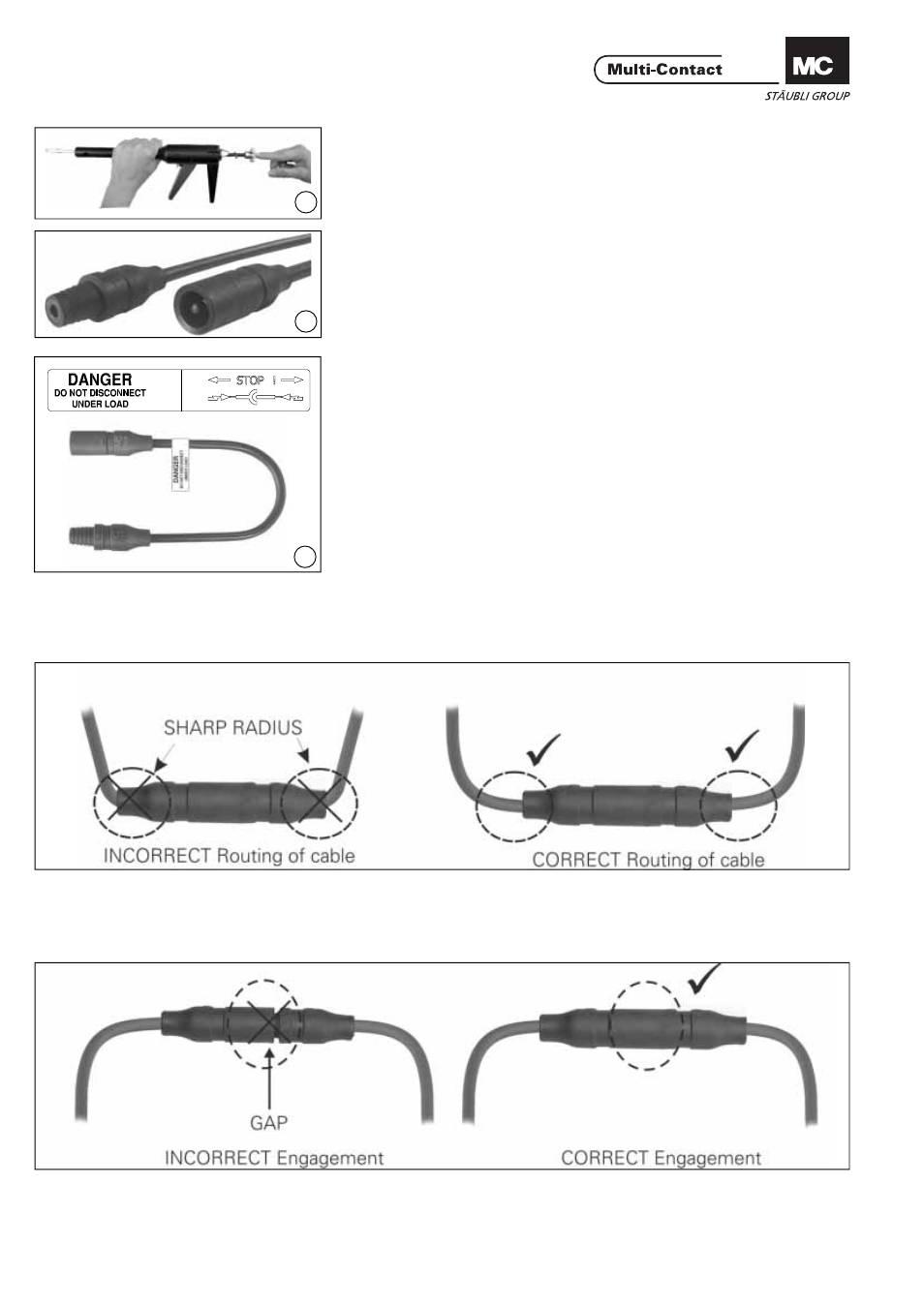
(ill. 18)
Coller l’autocollant„DANGER – DO
NOT DISCONNECT UNDER LOAD“ à
proximité du raccord mâle PV.
(ill. 18)
Affi x the supplied sticker “DANGER
– DO NOT DISCONNECT UNDER
LOAD” in the vicinity of the PV cou-
pler.
Disposition de câble
Cable routing
Se référer aux spécifi cations du
fabricant de câbles pour un rayon de
courbure minimal.
Refer to cable manufactures specifi ca-
tion for minimum bending radius.
Connexion
Engagement
Assurez-vous que les connecteurs
sont complètement fermés.
Check that the coupler parts are fully
engaged.