Multi-Contact MA259 Manuel d'utilisation
Page 4
Advanced Contact Technology
4 / 8
www.multi-contact.com
5
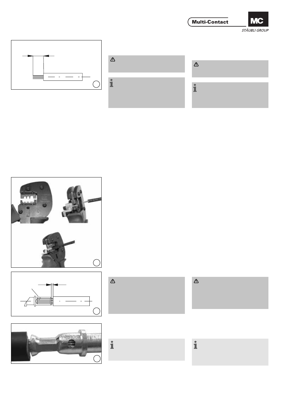
L
S
max. 1 mm
7
6
8
(ill. 5)
Dénuder le câble. Enlever l‘isolant du
câble sur une longueur de 6 à 7,5mm.
Attention
Veillez à ne pas couper les brins
lors de la dénudation.
Remarque:
Pour l’utilisation de la pince à
dénuder PV-AZM... ainsi que pour le
remplacement de jeux de couteaux,
reportez-vous à la notice d’utilisation
MA267 sur www.multi-contact.com
(ill. 5)
Strip cable insulation. Remove 6 to
7,5 mm of insulation from the end of
the cable.
Attention:
Do not cut individual strands at
stripping
Note:
For directions on the use of strip-
ping pliers PV-AZM... and changing
blade sets, see operating instruction
MA267 at www.multi-contact.com
Raccords à sertir
Crimp connections
Pour le raccordement des conduc-
teurs aux fûts à sertir des connecteurs
PV, nous recommandons l’emploi des
outils de sertissage indiqués. Les fûts
à sertir sont conçus pour des conduc-
teurs souples (classe 5 et 6 selon CEI
60228, DIN VDE 0295) de sections
2,5mm² à 4mm².
For connecting the conductors to the
crimp sleeves of the PV couplers, we
recommend using the stated crimping
tools. The crimping sleeves are de-
signed for fl exible wires (classes 5 and
6 according to IEC 60228, DIN VDE
0295) with conductor cross-sections
of 2.5mm² to 4mm².
Sertissage
Crimping
(ill. 6)
Introduisez la partie métallique de la
douille ou de la fi che dans le guide
pour la section correspondante. Intro-
duisez le câble jusqu’en butée dans
le fыt а sertir. Maintenez le câble dans
le fût.
(ill. 6)
Place the metal part of the female
or male coupler in the guide for the
appropriate cross section. Insert the
wire into the crimping sleeve as far as
it will go. Hold the wire in place in the
sleeve.
(ill. 7)
Attention
Tous les brins du câble doivent
être introduits proprement dans
le trou et être visibles dans
l‘orifi ce de contrôle S. La distance
maximale de 1 mm ne doit pas
être dépassée.
Fermez complètement la pince à sertir.
(ill. 7)
Attention:
All strands of the wires must be
correctly inserted into the bore-
hole and visible in sight hole S.
The max. distance of 1mm must
not be exceeded.
Completely close the crimping tool.
(ill. 8)
Contrôlez le sertissage visuellement.
Remarque:
pour l’utilisation de la pince à
sertir, voir la notice MA251 sur
www.multi-contact.com.
(ill. 8)
Visually check the crimp
Note:
for directions on the operation of
the crimping tool, please see operat-
ing instructions MA251 at www.
multi-contact.com