Multi-Contact MA201 Manuel d'utilisation
Page 10
Advanced Contact Technology
10 / 12 www.multi-contact.com
31
32
33
34
35
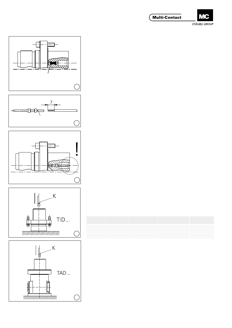
Montage des contacts pilotes
Assembly of pilot contacts
(ill. 31)
Retirer les bouchons d‘obturation
(bleus) à partir de la face d‘embro-
chage à l‘aide de l‘outil de démontage
(broche)MSA-WZ2(18.3009).
(ill. 31)
Remove, from the plug-in side, the
blue blind plugs from the contact
holes with the help of the pin extrac-
tiontoolMSA-WZ2(18.3009)
(ill. 32)
Dénuderlecâble(0,5 mm
2
-1,5 mm
2
)�
Longueuràdénuder:7 mm.Introduire
le câble dans le fыt а sertir du contact
pilote.PinceàsertirMES-CZ,Locator
MES-CZ1,5/2,Réglagedelapinceà
sertir (sélecteur):
(ill. 32)
Stripthecable(0,5 mm
2
-1,5 mm
2
)
Cablestrippinglength:7 mm
Insert cable in the crimping sleeve of
the pilot contact
CrimpingpliersMES-CZ,
LocatorMES-CZ1,5/2
Crimping position (selector):
1,5 mm
2
=Sel.Nr.6(AWG16)
1,0 mm
2
=Sel.Nr.5(AWG18)
0,75 mm
2
=Sel.Nr.5(AWG18)
0,5 mm
2
=Sel.Nr.4(AWG20)
1,5 mm
2
=Sel.Nr.6(AWG16)
1,0 mm
2
=Sel.Nr.5(AWG18)
0,75 mm
2
=Sel.Nr.5(AWG18)
0,5 mm
2
=Sel.Nr.4(AWG20)
Lecâbledoitêtrevisibleparl‘orifice
de contrôle avant et après sertissage�
Wiresmustbevisibleinthesighthole
before and after crimping�
Al‘aidedel‘outilME-WZ1,5/2
(18�3003), emmancher les contacts
pilotes dans leur logement respectif
par la face arrière jusqu‘à leur parfaite
mise en place�
Press the pilot contact, from the con-
nection side, into the contact chamber
until it snaps into place with the help
of the contact insertion tool ME-
WZ1,5/2(18.3003)
(ill. 33)
Contrôler visuellement la position
axiale des contacts pilotes:
Lesbrochesdoiventêtreàfleurou
aumaximum1 mmenretraitdela
surface frontale d‘embrochage�
(ill. 33)
A visual control of the axial mounting
position of the pilot contacts:
The front face of the pins should be
flushmountedorsetbackbyupto
max.1 mm.
Montage du codage hexago-
nal
Assembly of hex. coding pin
(ill. 34 - 35)
Emmancher le codage hexagonal (K)
dans la position souhaitée jusqu‘en
butée�
(ill. 34 - 35)
Press-in enclosed hex� coding pin (K)
in the desired position until it can be
heard engaging�
Bouchon d‘obturation
Blind plugs
Orifice de contrôle
Sight hole
Type
No. de Cde
Order no.
Largeur de clé
Across flats
Système de montage
Fitting system
Convient pour
fits to
6KT�KOD�A
31�5300
SW9
Emmancher
Press-in
TID-B/...,
TAD/���
6KT�KOD�S
31�5301
SW11
TID-B150...