À fl eur fl ush, Montage du câble cable assembly, Contrôle du montage checking of assembly – Multi-Contact MA213-03 Manuel d'utilisation
Page 4: Démontage des contacts extraction of contacts
Advanced Contact Technology
4 / 4
www.multi-contact.com
8
LW L-B
LW L-S
3
2
1
3
2
1
9
10
4.
2
21
11
12
POF-B
POF-S
MC
MC
POF-B
POF-S
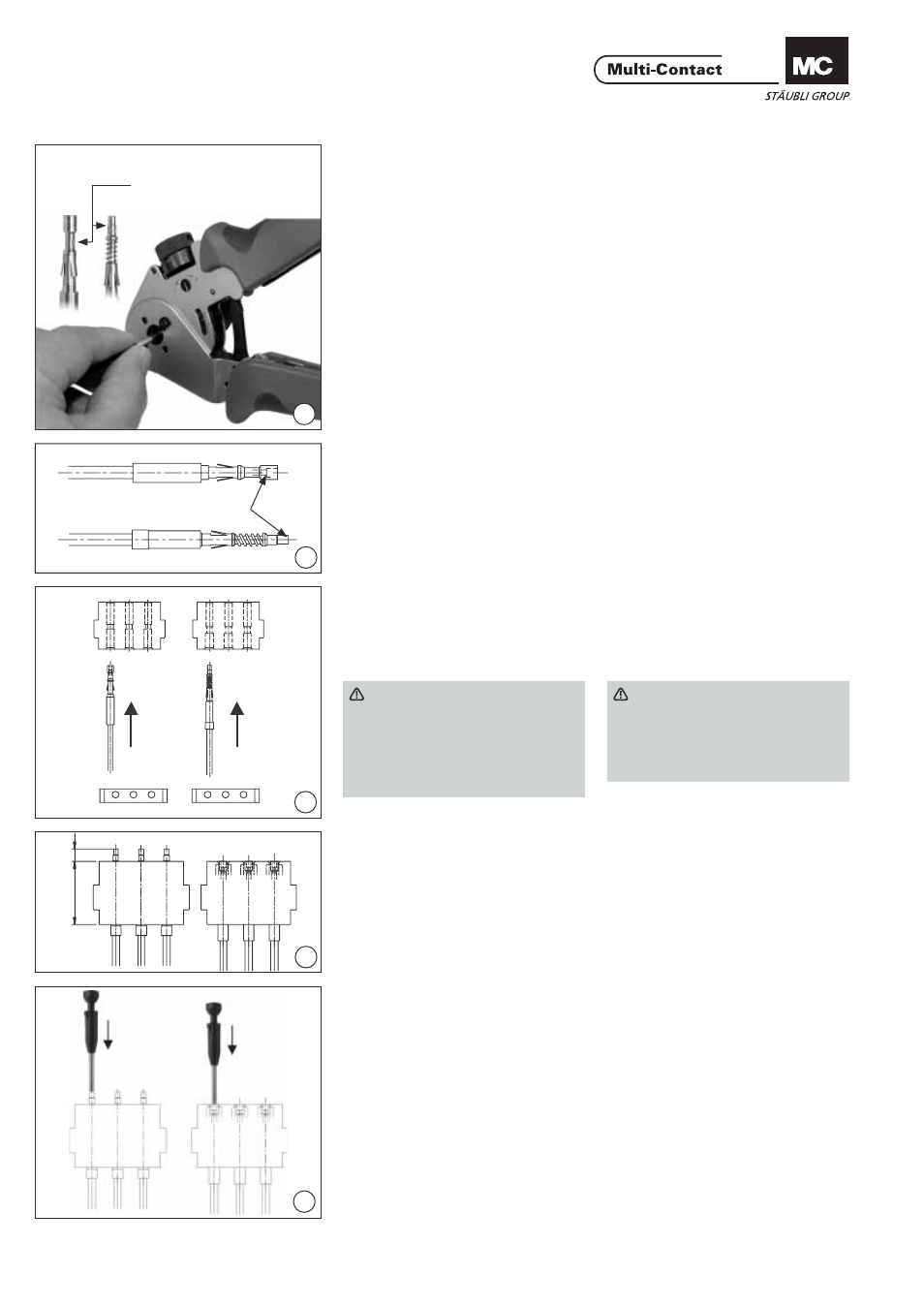
Montage du câble
Cable assembly
(ill. 8)
Pour sertir, se référer au mode d‘em-
ploi MA065 de la pince à sertir.
(www.multi-contact.com)
Positionner le contact POF en bu-
tée dans la pince et fermer la pince
jusqu’au premier cran. Introduire le
câble POF préparé dans le contact
jusqu’en butée, exercer une pression
sur le câble et le contact et fermer
entièrement la pince. En relâchant
la pince, cette dernière doit s’ouvrir
spontanément, garantissant ainsi un
bon sertissage.
(ill. 8)
For crimping see the operating
instructions of the crimping pliers
MA065 (www.multi-contact.com)
Insert the POF contact into the crimp
place up to the stop and close the
crimp pliers up to the fi rst snap-in
position.
Insert the prepared cable into the POF
contact up to the stop, gently push in
the cable and the contact and close
the pliers completely. After crimping
the pliers must open automaticaly.
This ensures that the crimp procedure
has been correctly executed.
(ill. 9)
Contrôle: Les câbles doivent être à
fl eur (voir fl èche) de la face avant des
connecteurs.
(ill. 9)
Check: The cables must be fl ush (see
arrow) with the front side.
(ill. 10)
Introduire les contacts manuellement
par l‘arrière du support de contacts
jusqu‘à l‘encliquetage. (La face arrière
correspond au côté sans logo „MC“).
(ill. 10)
Manually insert the contacts into the
contact carriers from the back until
they engage. (The back is the side
without “MC” logos).
Attention
Les supports pour contacts mâles
et femelles sont différents. POF-S
pour contacts mâles, POF-B pour
contacts femelles.
Contrôler l‘encliquetage correct
en tirant sur le câble.
Achtung
Plugs and sockets have different
contact carriers. POF-S for pins,
POF-B for sockets.
Check correct engagement by
pulling the cable.
Contrôle du montage
Checking of assembly
(ill. 11)
Vérifi er le montage correct des
contacts en contrôlant la cote
4,2mm (pour les contacts mâles).
Les contacts femelles doivent être à
fl eur de la face avant du support de
contacts.
(ill. 11)
The correct engagement of the
contacts must be checked with the
dimension 4.2mm (for pins). The sock-
ets must be fl ush with the top edge of
the contact carrier.
Démontage des contacts
Extraction of contacts
(ill. 12)
Introduire par l’avant l‘outil de dé-
montage jusqu‘en butée et sortir les
contacts en tirant sur le câble.
(ill. 12)
Insert extraction tool into the contact
carrier from the plugging side as far as
it will go and pull out the contacts.
Position de sertissage
Crimp position
à fl eur
fl ush
© b
y
Multi-Contact A
G, Switz
erland – MA213-03 – 06.2012, Inde
x d
, Global Communications – Modi
fi
cations sous réserv
e / Subject to alterations