Fig. 2, Fig. 2a, Fig.2 – Medal Sports WMC1444117 Manuel d'utilisation
Page 7
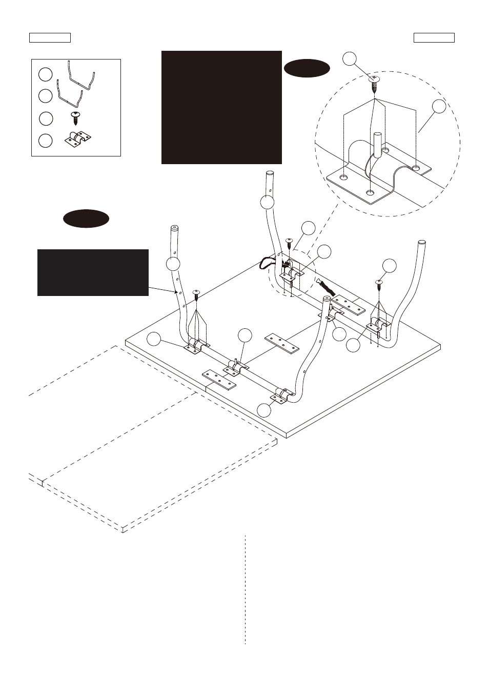
FIG.2
6. Place one Curved Outer Leg with Cap (#5) on the player
end of the table half and one Curved Inner Leg with Cap
(#6) on the center end of the table half.
7. Attach the Leg Bracket (#29) to the Curved Outer Leg
(#5) and the Curved Inner Leg (#6) using Screws
(#23).
See FIG. 2A.
8. Repeat the above steps for the other table half.
FIG.2
6. Placez un Pied extérieur courbé avec capuchon (#5) sur
le Joueur en bout de table et un Pied intérieur courbé
avec capuchon (#6) à l’extrémité centrale de la moitié
de table.
7. Fixez le Chevron de pied (#29) au Pied extérieur
courbé (#5) et le Pied intérieur courbé (#6) avec des Vis
(#23).
Voir FIG. 2A.
8. Répétez les étapes précédentes sur l’autre moitié de table.
5
6
X 2
X 2
29
X 12
23
X 48
Player
/ Joueur
Player
/ Joueur
Center /
Centre
29
29
23
29
29
6
FIG. 2
23
23
5
NOTE: Make sure that the
oval cut-out in the Leg
Bracket are facing the
center of the table for
proper installation.
NOTE: Assurez-vous que la
découpe ovale du Chevron
de pied fait face au centre
de la table pour une
installation appropriée.
FIG. 2A
29
29
29
This is hole for “Gravity
Lock” assembly.
/ Orifice pourl’assemblage
du “Verrou de gravité”.
Français
English
(Suite page suivante.)
www.themdsports.com
1444117
6
(Continued on the next page.)