Termination 4-wire 4-wire, Connection rs-485, Connection rs-422 – Westermo TD-32 B Manuel d'utilisation
Page 5
6
6178-2010
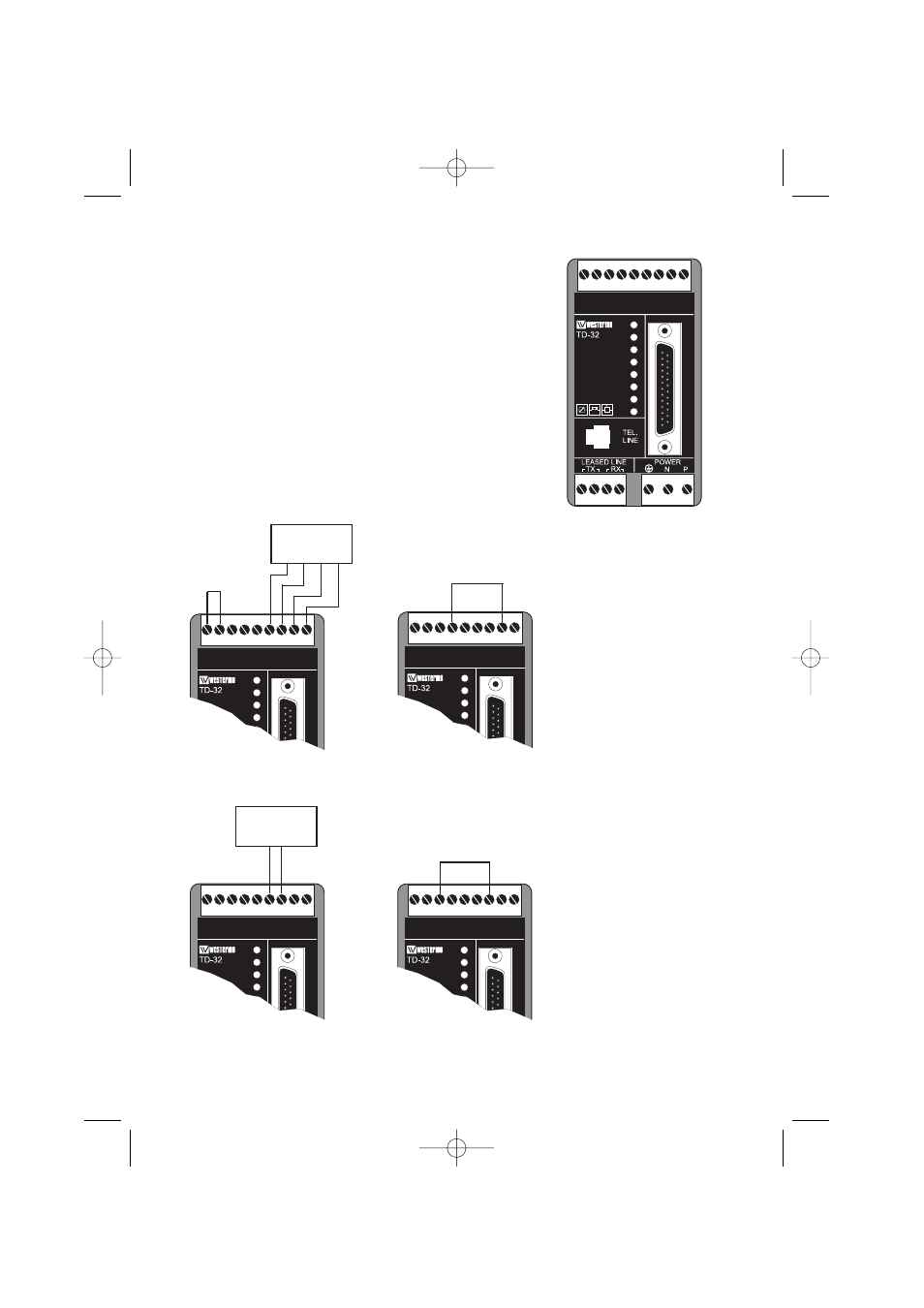
Termination
2-wire
TD-32 B/485 (RS-422/485 interface)
As an option the TD-32 B can be supplied with an RS-422/485 inter-
face. This product is referred to as the TD-32 B/485.
On the TD-32 B/485 the RS-232/V.24 connection on the screw termi-
nal on upper front side of the unit has been replaced with an RS-
422/485 interface. All other features remain identical
between the standard TD-32 B and TD-32 B/485.
The TD-32 B/485 can still be connected to an RS-232/V.24 port using
the 25-pole D-sub. Please note that there is no galvanic isolation
between the RS-232 and the RS-422/485 ports so they should not be
connected simultaneously.
The RS-422/485 connections are made as shown below.
Please note that the selection of 2 or 4 wire and termination or no termi-
nation is done by linking between some of the screw terminals.
The default switch settings on a TD-32 B/485 is: SW3:1 and SW3:6
set to ON, the rest is OFF.
R+
RS 422/485
R-
T+
T-
GND
PWR
TD
RD
RTS
DCD
LINE
ANS
REL
T4
T2
V24/RS232-C
WIRE
2/4
S1
1
2
3
4
5
6
7
8
9
B
TD-32 B/485
R+
RS 422/485
R-
T+
T-
GND
PWR
TD
RD
RTS
DCD
LINE
ANS
T4
T2
V24/RS232-C
WIRE
2/4
S1
1
2
3
4
5
6
7
8
9
B
R+
RS 422/485
R-
T+
T-
GND
PWR
TD
RD
RTS
DCD
LINE
ANS
T4
T2
V24/RS232-C
WIRE
2/4
S1
1
2
3
4
5
6
7
8
9
B
Termination
4-wire
4-wire
R+
RS 422/485
R-
T+
T-
GND
PWR
TD
RD
RTS
DCD
LINE
ANS
T4
T2
V24/RS232-C
WIRE
2/4
S1
1
2
3
4
5
6
7
8
9
B
Connection
RS-485
R+
RS 422/485
R-
T+
T-
GND
PWR
TD
RD
RTS
DCD
LINE
ANS
T4
T2
V24/RS232-C
WIRE
2/4
S1
1
2
3
4
5
6
7
8
9
B
Connection
RS-422
TD-32B_V34_6178-2010_REVC.qxd 05-08-29 11.15 Sida 6