Schéma des connexions électriques, Th ms1, Pcb2 pcb1 – REMKO RKL 460 Manuel d'utilisation
Page 13: Wm ms2, Cn6 cn7
13
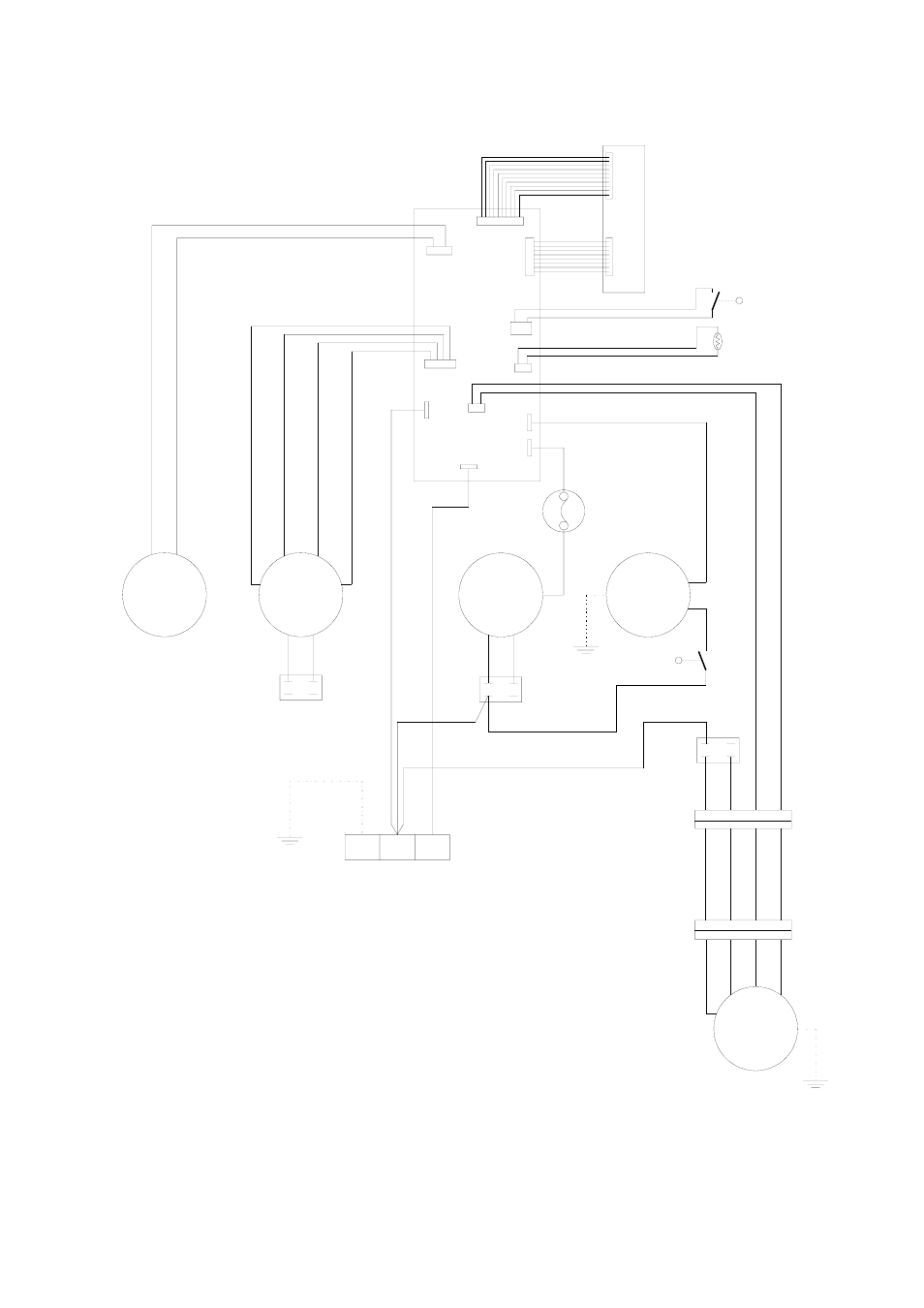
Schéma des connexions électriques
Sous réserve de modifications de cotes et de construction dans le sens du progrès technique.
CM
PE
N
L
CX1
SM
FM1
CM
FM2
CX3
CX2
OLP
AC2
WM
AC1
CN1
CN5
CN4
TH
MS1
P001B
P002B
CN2
PCB2
PCB1
R
BK
BU
BU
BR
W
BU
BU
BU
R
R
R
GR
BK
BR BR
Legende
PCB2 = Steuerplatine
SM
= Swing-Motor
FM1
= Lüftermotor Innengerät
FM2
= Lüftermotor Außenteil
WM
= Kondensatpumpe
CM
= Verdichter
OLP
= Verdichterschutz
CX1
= Kondensator (FM1)
CX2
= Kondensator (FM2)
CX3
= Kondensator (CM)
TH
= Temperatursensor
MS1
= Mikroschalter (Tank voll)
MS2
= Mikroschalter (Pumpe)
PCB1 = Bedientableau
CN3
WM
MS2
BU
BU
BR
BK
Y
BU BR
BK
Y
CN6
CN7
C
S
R
OR
W
BU
Y
BU BR
BK
Y
Farbkennzeichnung
W
= Weiß
R
= Rot
BU
= Blau
BR
= Braun
BK
= Schwarz
GR
= Grau
OR
= Orange
Y
= Gelb
Légende
PCB1 = Tableau de commande
PCB2 = Platine de commande
SM
= Moteur à mouvement alternatif
FM1
= Moteur du ventilateur, appareil intérieur
FM2
= Moteur du ventilateur, partie extérieure
WM
= Pompe de condensat
CM =
Condensateur
OLP = Protection
condensateur
CX1 = Condensateur
(FM1)
CX2 = Condensateur
(FM2)
CX3 = Condensateur
(CM)
TH
= Capteur de température
MS1
= Micro-rupteur (collecteur plein)
MS2 = Micro-rupteur
(pompe)
Codage des couleurs
Y =
jaune
W = blanc
R =
rouge
BU = bleu
BR = brun
BK = noir
GR = gris
OR = orange