Forza 48 Inch Freestanding Professional Gas Range Installation Instructions Manuel d'utilisation
Page 38
38
CONVERSION FROM NATURAL GAS TO LIQUID GAS
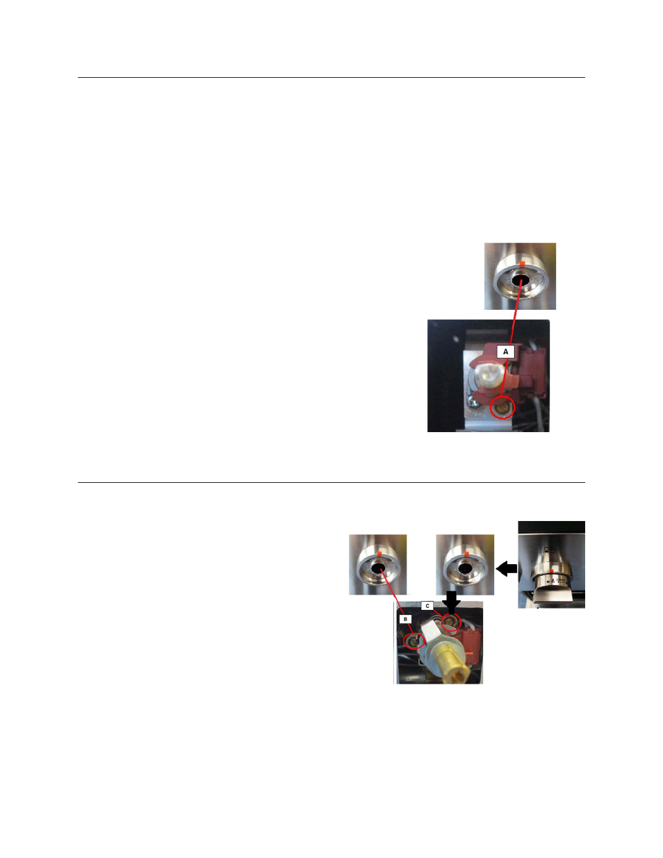
Insert the screwdriver in the hole in the front wall of the instrument panel and turn regulation screw A clockwise.
Proper adjustment will produce a stable, steady blue flame of minimum size.
The final adjustment should be checked by turning the knob from high to low several times without extinguishing the flame.
This adjustment, at low setting, will automatically provide the proper flame size at medium setting.
After conversion steps have been completed, check the appearance of each burner’s flame at the HI and LO settings, if the
flames appear too large or too small review each step to make sure it was completed correctly.
NOTE:
To obtain the correct minimum setting with LP gas, turn clockwise tightening the valve(s) fully with the thin-blade screw-
driver into the recess behind control knob (A and / or B).
1)
Remove control knob from valve stem.
2) Insert a slender, thin-blade screwdriver into the recess behind the control knob
and engage blade with slot in adjusting screw A single flame.
ADJUSTMENT FOR BURNERS WITH ONE OR TWO FLAME RINGS:
1)
Remove control knob from valve stem.
2) Insert a slender, thin-blade screwdriver into the recess
behind the control knob and engage blade with slot in
adjusting screw B double flame;
To adjust the screw C the procedure is different:
1)
Rotate the knob to 90° (Max position);
2) Remove control knob in this position.
3) Insert a slender, thin-blade screwdriver into the recess
behind the control knob and engage blade with slot in
adjusting screw C double flame;
Figure 3: The burner tap
with double flame
Figure 2: The burner tap
with single flame