Kichler 42944 Manuel d'utilisation
Page 2
11) Connecter les fils (connecteurs non fournis). Se reporter au tableau
ci-dessous pour faire les connexions.
12) Appliquer l’armature d’éclairage au plafond en introduisant prudemment
les vis de fixation dans les trous.
13) Visser le lustre au plafond á l’aide des rondelles-frein et des boules filetées.
14) Placer le verre sur la douille.
15) Fixer l’anneau de prise sur l’outil pour l’anneau de la douille.
16) Abaisser l’outil de l’anneau de la douille avec l’anneau de la douille attaché
en bas du verre. Resserrer l’anneau de la douille pour bien fixer le verre.
(NE PAS serrer avec excès).
SEMI FLUSH INSTALLATION
1) Remove canopy from end of arms by unthreading hexnuts and
removing lockwashers that are holding arms to canopy. (Lockwashers
and hexnuts will be used again to install new canopy.)
2) Remove finial, hex coupling and lockwashers from center of canopy.
(Finial and one lockwasher will be used again on new canopy.)
3) Using canopy supplied for Semi Flush Installation, attach arms to
canopy with lockwashers and hexnuts.
4) Thread small threaded pipe (from parts bag) into finial. Pass end of
threaded pipe up through center hole in canopy.
5) Slip one lockwasher over end of threaded pipe protruding from inside
canopy. Thread hexnut (from parts bag) onto threaded pipe. Tighten
hexnut to secure finial in place.
6) Align holes in plate on bottom of arm with holes on inside of ring.
7) Thread screws into holes in plate and into ring. Tighten screws to
secure arm to ring. Repeat for remaining arms.
8) TURN OFF POWER.
IMPORTANT: Before you start, NEVER attempt any work without
shutting off the electricity until the work is done.
a) Go to the main fuse, or circuit breaker, box in your home. Place
the main power switch in the “OFF” position.
b) Unscrew the fuse(s), or switch “OFF” the circuit breaker switch(s),
that control the power to the fixture or room that you are working on.
c) Place the wall switch in the “OFF” position. If the fixture to be
replaced has a switch or pull chain, place those in the “OFF”
position.
9) Find the appropriate threaded holes on mounting strap. Assemble
mounting screws into threaded holes.
10) Attach mounting strap to outlet box. (Screws not provided). Mounting
strap can be adjusted to suit position of fixture.
11) Make wire connections (connectors not provided). Reference chart
below for correct connections and wire accordingly.
12) Push fixture to ceiling, carefully passing mounting screws through holes
in canopy.
13) Secure fixture to ceiling with threaded balls.
14) Set glass down over sockets.
15) Attach socket ring to socket ring tool.
16) Lower socket ring tool with socket ring attached down through glass.
Thread socket ring onto socket. Tighten socket ring to secure glass in
place. (DO NOT over tighten.)
LES INSTRUCTIONS D’INSTALLATION SEMI-ENCASTRÉE
1) Enlever le cache de l’extrémité des bras en dévissant les écrous
hexagonaux et en retirant les rondelles de blocage fixant les bras au
cache. (Les rondelles de blocage et les écrous hexagonaux seront
réutilisés pour installer un nouveau cache).
2) Enlever l’ornement, l’accouplement hex et les rondelles de blocage du
centre du cache. (L’ornement et une rondelle de blocage seront
réutilisés sur un nouveau cache).
3) En se servant du cache fourni pour une installation semi-encastrée,
fixer les bras au cache à l’aide des rondelles de blocage et des écrous
hexagonaux.
4) Visser le petit tube fileté (du sac de pièces) dans l’ornement. Passer
l’extrémité du tube fileté par le trou situé dans le cache.
5) Passer une rondelle de blocage sur l’extrémité du tube fileté ressortant
de l’intérieur du cache. Visser l’écrou hexagonal (du sac de pièces) sur
le tube fileté. Serrer l’écrou hexagonal pour fixer l’ornement.
6) Aligner les trous dans la plaque sur la partie inférieure du bras avec
ceux situés à l’intérieur de l’anneau.
7) Serrer les vis dans les trous de la plaque et dans l’anneau. Serrer les
vis pour fixer le bras à l’anneau. Répéter l’opération pour les autres
bras.
8) COUPER LE COURANT.
IMPORTANT: TOUJOURS couper l’électricité avant de commencer le
travail.
a) Localiser le coffret à fusibles ou le disjoncteur du domicile. Mettre
l’interrupteur principal en position d’Arrêt.
b) Dévisser le ou les fusibles (ou mettre le disjoncteur sur Arrêt) qui
contrôlent l’alimentation vers le luminaire ou la pièce dans
laquelle le travail est effectué.
c) Mettre l’interrupteur mural en position d’Arrêt. Si le luminaire à
remplacer est doté d’un interrupteur ou d’une chaîne connectée à
l‘interrupteur, placer ces éléments en position d’Arrêt.
9) Trouver les trous filetés appropriés sur la barrette de montage. Vissez
les vis de montage dans les trous filetés.
10) Visser la barrette de montage à la boite de jonction. (Vis non fournies).
La barrette de montage peut etre ajustée pour convenir à la position de
l’applique.
Connect Black or
Red Supply Wire to:
Connect
White Supply Wire to:
Black
White
*Parallel cord (round & smooth)
*Parallel cord (square & ridged)
Clear, Brown, Gold or Black
without tracer
Clear, Brown, Gold or Black
with tracer
Insulated wire (other than green)
with copper conductor
Insulated wire (other than green)
with silver conductor
*Note: When parallel wires (SPT I & SPT II)
are used. The neutral wire is square shaped
or ridged and the other wire will be round in
shape or smooth (see illus.)
Neutral Wire
SEE OTHER SIDE FOR RIGID STEM MOUNT
AND LOOP/CHAIN LINK INSTALLATIONS.
VOIR AU VERSO POUR LES INSTRUCTIONS
D’INSTALLATION MONTAGE TIGE RIGIDE ET
D’INSTALLATION DES LIENS EN BOUCLE/
MAILLON.
Date Issued: 7/15/11
IS-42944-CB
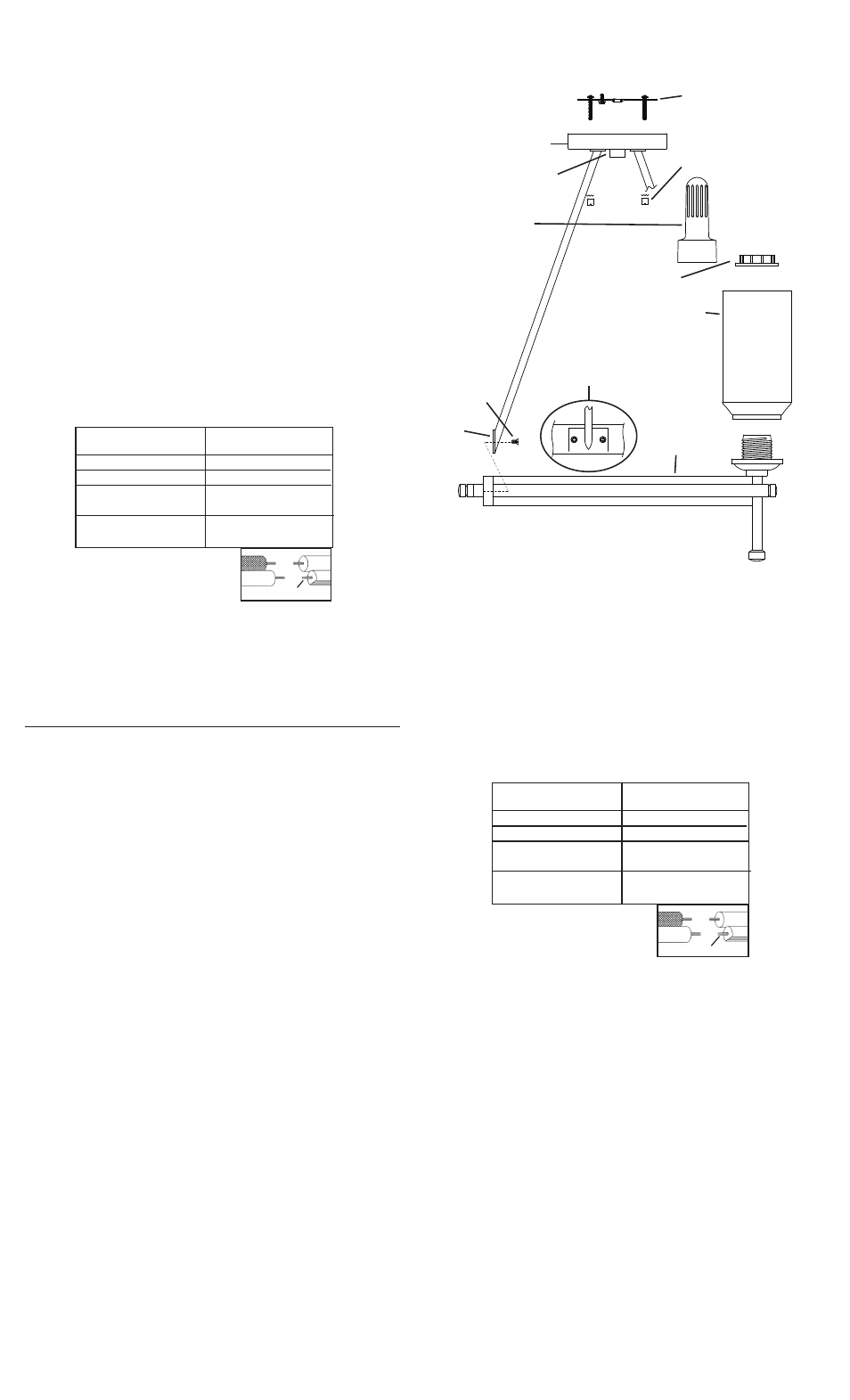
GLASS
VERRE
SCREW
VIS
FINIAL
ORNEMENT
RING
ANNEAU
SEMI FLUSH CEILING MOUNT
INSTALACIÓN A SEMIRRÁS EN EL CIELO RASO
Connecter le fil noir ou
rouge de la boite
Connecter le fil blanc de la boîte
A Noir
A Blanc
*Au cordon parallèle (rond et lisse)
*Au cordon parallele (à angles droits el strié)
Au bransparent, doré, marron, ou
noir sans fil distinctif
Au transparent, doré, marron, ou
noir avec un til distinctif
Fil isolé (sauf fil vert) avec
conducteur en cuivre
Fil isolé (sauf fil vert) avec
conducteur en argent
*Remarque: Avec emploi d’un fil paralléle
(SPT I et SPT II). Le fil neutre est á angles
droits ou strié et l’autre fil doit étre rond ou
lisse (Voir le schéma).
Fil Neutre
SOCKET RING
BAGUE DE LA DOUILLE
SOCKET RING TOOL
OUTIL DE L’ANNEAU
DE LA DOUILLE
PLATE
PLAQUE
MOUNTING STRAP
PATTE DE FIXATION
CANOPY
CACHE
THREADED BALL
BOULE FILETÉ
ARM/RING DETAIL
DÉTAIL DU BRAS/
ANNEAU